FRONT CRANKSHAFT OIL SEAL INSTALLATION

-
INSTALL FRONT CRANKSHAFT OIL SEAL
-
Apply MP grease to the lip of a new oil seal.
-
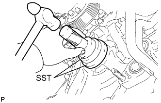
Using SST and a hammer, tap in the oil seal to a depth between 0 and 1.0 mm (0 and 0.0394 in.) from the timing chain cover edge.
- SST
- 09223-22010
- 09506-35010
Note
-
Keep the lip free from foreign matter.
-
Do not tap the oil seal at an angle.
-
-
INSTALL CRANKSHAFT TIMING GEAR KEY
-
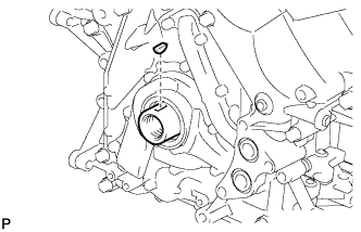
Install the crankshaft timing gear key.
-
-
INSTALL CRANKSHAFT PULLEY
-
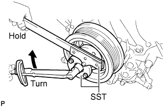
Align the pulley set key with the key groove of the pulley, and slide on the pulley.
-
Using SST, install the pulley set bolt.
- SST
- 09213-70011 ( 09213-70020 )
- 09330-00021
- Torque:
- 300 N*m { 3059 kgf*cm, 221 ft.*lbf }
-
-
INSTALL OIL FILTER BRACKET (w/ Oil Cooler)
-
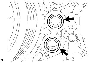
Apply a light coat of engine oil to 2 new O-rings.
-
Install the 2 O-rings to the timing chain cover.
-
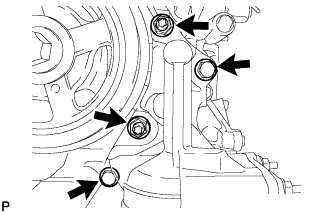
Install the oil filter bracket with the 2 nuts and 2 bolts.
- Torque:
- 35 N*m { 357 kgf*cm, 26 ft.*lbf }
-
-
INSTALL NO. 1 OIL COOLER BRACKET (w/ Oil Cooler)
-
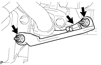
Connect the ground wire to the cylinder block.
-
Install the oil cooler bracket with the 2 nuts.
- Torque:
- 21 N*m { 214 kgf*cm, 15 ft.*lbf }
-
-
CONNECT NO. 2 WATER BY-PASS PIPE SUB-ASSEMBLY (w/ Oil Cooler)
-
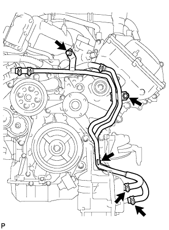
Connect the 2 water by-pass hoses to the oil cooler.
-
Install the 3 by-pass pipe bolts.
- Torque:
- 10 N*m { 102 kgf*cm, 7 ft.*lbf }
-
-
CONNECT COOLER COMPRESSOR ASSEMBLY (w/ Oil Cooler)
-
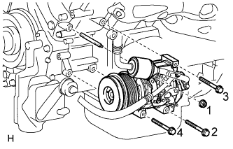
Install the cooler compressor with the stud bolt.
- Torque:
- 10 N*m { 102 kgf*cm, 7 ft.*lbf }
-
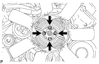
Install the 3 bolts and nut.
- Torque:
- 25 N*m { 250 kgf*cm, 18 ft.*lbf }
Note
Tighten the bolts and nut in the order shown in the illustration to install the cooler compressor.
-
-
INSTALL OIL FILTER BRACKET (w/o Oil Cooler)
-
Apply a light coat of engine oil to 2 new O-rings.
-
Install the 2 O-rings to the timing chain cover.
-
Install the oil filter bracket with the 2 nuts and 2 bolts.
- Torque:
- 35 N*m { 357 kgf*cm, 26 ft.*lbf }
-
-
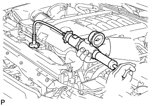
INSTALL OIL PRESSURE SENDER GAUGE ASSEMBLY
-
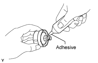
Apply adhesive to 2 or 3 threads of the oil pressure sender gauge.
Adhesive Toyota Genuine Adhesive 1344, Three Bond 1344 or equivalent Note
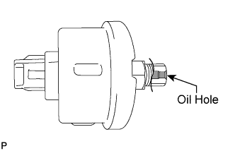
Do not allow adhesive to contact the oil hole.
-
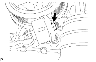
Install the oil pressure sender gauge.
- Torque:
- 15 N*m { 153 kgf*cm, 11 ft.*lbf }
Note
Do not start the engine within 1 hour after installation.
-
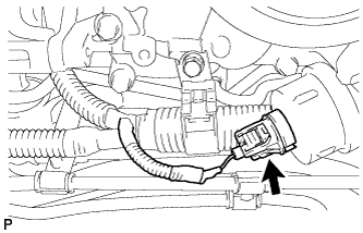
Connect the sender gauge connector.
-
-
INSTALL FAN SHROUD
-
Install the fan pulley.
-
Place the shroud together with the coupling fan between the radiator and engine.
Note
Be careful not to damage the radiator core.
-
Temporarily install the fluid coupling fan to the fluid coupling bracket with the 4 nuts. Tighten the nuts as much as possible by hand.
-
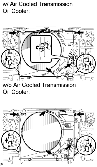
Attach the claws of the shroud to the radiator as shown in the illustration.
-
Install the shroud with the 2 bolts.
- Torque:
- 8.0 N*m { 82 kgf*cm, 71 in.*lbf }
-
Connect the oil cooler tube to the fan shroud with the 2 bolts.
- Torque:
- 5.0 N*m { 51 kgf*cm, 44 in.*lbf }
-
w/ Air Cooled Transmission Oil Cooler:
Pass the hose through the flexible hose clamp and close the clamp as shown in the illustration.
-
Connect the reservoir hose to the upper radiator tank.
-
Install the fan and generator V belt Click here.
-
Tighten the 4 nuts of the fluid coupling fan.
- Torque:
- 21 N*m { 214 kgf*cm, 15 ft.*lbf }
-
-
INSTALL NO. 1 RADIATOR HOSE
-
ADD ENGINE COOLANT
-
Add engine coolant.
Standard Capacity Item Specified Condition with transmission oil cooler 16.7 liters (17.6 US qts, 14.7 Imp. qts) without transmission oil cooler 16.2 liters (17.1 US qts, 14.3 Imp. qts) Note
Do not substitute plain water for engine coolant.
Tech Tips
TOYOTA vehicles are filled with TOYOTA SLLC at the factory. In order to avoid damage to the engine cooling system and other technical problems, only use TOYOTA SLLC or similar high quality ethylene glycol based non-silicate, non-amine, non-nitrite, non-borate coolant with long-life hybrid organic acid technology (coolant with long-life hybrid organic acid technology consists of a combination of low phosphates and organic acids).
-
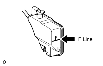
Slowly pour coolant into the radiator reservoir until it reaches the F line.
-
Install the reservoir cap.
-
Press the No. 1 and No. 2 radiator hoses several times by hand, and then check the coolant level. If the coolant level is low, add coolant.
-
Install the radiator cap.
-
Start the engine and warm it up until the thermostat opens.
Note
Switch off the A/C.
-
Maintain the engine speed at 2000 to 2500 rpm.
Note
-
Make sure that the radiator reservoir still has some coolant in it.
-
Pay attention to the needle of the water temperature meter. Make sure that the needle does not show an abnormally high temperature.
-
If there is not enough coolant, the engine may burn out or overheat.
-
Immediately after starting the engine, if the radiator reservoir does not have any coolant, perform the following: 1) stop the engine, 2) wait until the coolant has cooled down, and 3) add coolant until the coolant is filled to the F line.
-
Run the engine at 2000 rpm until the coolant level has stabilized.
-
-
Press the No. 1 and No. 2 radiator hoses several times by hand to bleed air.
CAUTION:
-
Wear protective gloves.
-
Be careful as the radiator hoses are hot.
-
Keep your hands away from the fan.
-
-
Stop the engine, and wait until the engine coolant cools down to ambient temperature.
CAUTION:
Do not remove the radiator cap while the engine and radiator are still hot. Pressurized, hot engine coolant and steam may be released and cause serious burns.
-
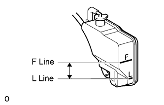
Check that the coolant level is between the F and L lines.
If the coolant level is below the L line, repeat all of the procedures above.
If the coolant level is above the F line, drain coolant so that the coolant level is between the F and L lines.
-
-
INSPECT FOR COOLANT LEAK
-
Fill the radiator with coolant and attach a radiator cap tester.
-
Warm up the engine.
-
Using the radiator cap tester, increase the pressure inside the radiator to 123 kPa (1.3 kgf/cm2, 18 psi), and check that the pressure does not drop.
If the pressure drops, check the hoses, radiator and water pump for leaks. If no external leaks are found, check the heater core, cylinder block and head.
-
-
INSPECT FOR OIL LEAK
-
Start the engine. Make sure that there are no oil leaks from the area that was worked on.
-
-
INSPECT ENGINE OIL LEVEL
-
Warm up the engine. Then stop the engine and wait for 5 minutes.
-
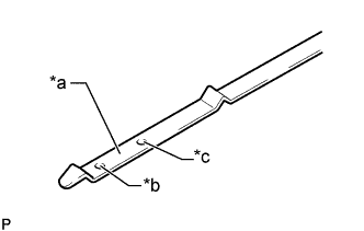
Text in Illustration *a Measuring Surface *b Low Level Mark *c Full Level Mark Check that the engine oil level is between the dipstick low level mark and full level mark.
If the level is low, check for leakage and add oil up to the full level mark.
Note
Do not fill engine oil above the full level mark.
Tech Tips
A certain amount of engine oil will be consumed while driving. In the following situations, oil consumption may increase, and engine oil may need to be refilled in between oil maintenance intervals.
-
When the engine is new, for example directly after purchasing the vehicle or after replacing the engine.
-
If low quality oil or oil of an inappropriate viscosity is used.
-
When driving at high engine speed or with a heavy load, (when towing, or), when driving while accelerating or decelerating frequently.
-
When leaving the idling for a long time, or when driving frequently through heavy traffic.
When judging the amount of oil consumption, keep in mind that the oil may have become diluted, making it difficult to judge the true level accurately.
-
-
-
INSTALL NO. 1 ENGINE UNDER COVER SUB-ASSEMBLY
-
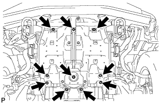
Install the No. 1 engine under cover with the 10 bolts.
- Torque:
- 29 N*m { 296 kgf*cm, 21 ft.*lbf }
-
-
INSTALL FRONT FENDER SPLASH SHIELD SUB-ASSEMBLY LH
-
Push in the clip to install the front fender splash shield sub-assembly LH.
-
Install the 3 bolts and 2 screws.
-
-
INSTALL FRONT FENDER SPLASH SHIELD SUB-ASSEMBLY RH
Tech Tips
Use the same procedure described for the LH side.
-
INSTALL V-BANK COVER SUB-ASSEMBLY
-
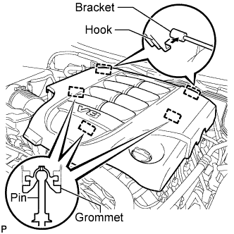
Attach the 2 V-bank cover hooks to the bracket. Then align the 3 V-bank cover grommets with the 3 pins, and press down on the V-bank cover to attach the pins.
-
-
INSTALL UPPER RADIATOR SUPPORT SEAL
-
Install the upper radiator support seal with the 3 clips.
-
-
INSTALL ENGINE ROOM SIDE COVER RH
-
Install the engine room side cover RH with the 7 clips.
-
-
INSTALL ENGINE ROOM SIDE COVER LH
-
Install the engine room side cover LH with the 7 clips.
-