FRONT CRANKSHAFT OIL SEAL REMOVAL

-
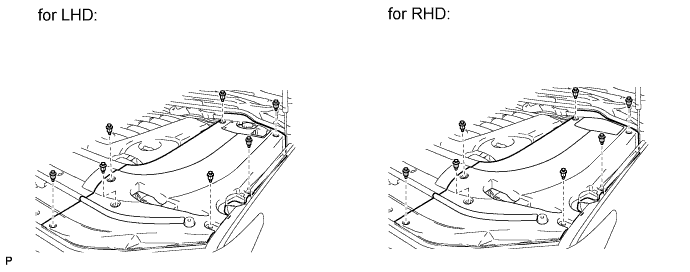
REMOVE ENGINE ROOM SIDE COVER LH
-
Remove the 7 clips and engine room side cover LH.
-
-
REMOVE ENGINE ROOM SIDE COVER RH
-
Remove the 7 clips and engine room side cover RH.
-
-
REMOVE UPPER RADIATOR SUPPORT SEAL
-
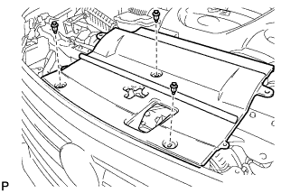
Remove the 3 clips and upper radiator support seal.
-
-
REMOVE V-BANK COVER SUB-ASSEMBLY
-
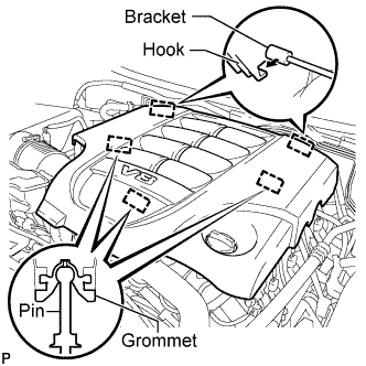
Raise the front of the V-bank cover to detach the 3 pins. Then remove the 2 V-bank cover hooks from the bracket, and remove the V-bank cover.
-
-
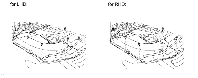
REMOVE FRONT FENDER SPLASH SHIELD SUB-ASSEMBLY LH
-
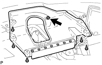
Remove the 3 bolts and 2 screws.
-
Turn the clip indicated by the arrow in the illustration to remove the front fender splash shield sub-assembly LH.
-
-
REMOVE FRONT FENDER SPLASH SHIELD SUB-ASSEMBLY RH
Tech Tips
Use the same procedure described for the LH side.
-
REMOVE NO. 1 ENGINE UNDER COVER SUB-ASSEMBLY
-
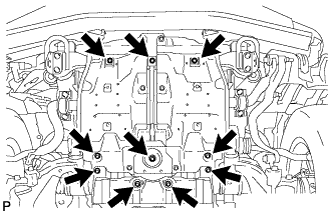
Remove the 10 bolts and No. 1 engine under cover.
-
-
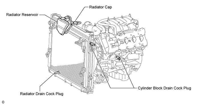
DRAIN ENGINE COOLANT
CAUTION:
Do not remove the radiator cap while the engine and radiator are still hot. Pressurized, hot engine coolant and steam may be released and cause serious burns.
-
Loosen the radiator drain cock plug.
Tech Tips
Collect the coolant in a container and dispose of it according to the regulations in your area.
-
Remove the radiator cap. Then drain the coolant from the radiator.
-
Loosen the 2 cylinder block drain cock plugs. Then drain the coolant from the engine.
-
Tighten the 2 cylinder block drain cock plugs.
- Torque:
- 13 N*m { 130 kgf*cm, 10 ft.*lbf }
-
Tighten the radiator drain cock plug by hand.
-
-
REMOVE NO. 1 RADIATOR HOSE
-
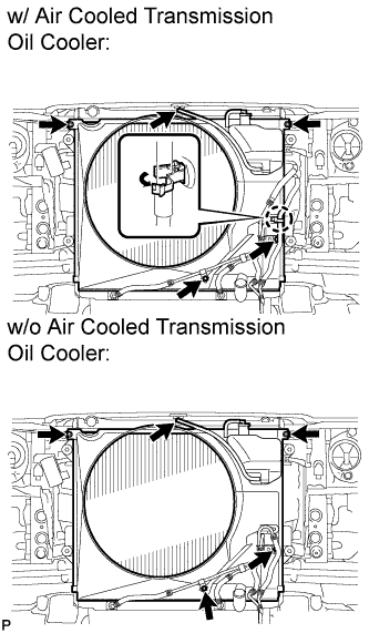
REMOVE FAN SHROUD
-
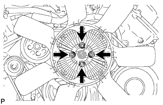
Loosen the 4 nuts holding the fluid coupling fan.
-
Remove the fan and generator V belt Click here.
-
Disconnect the reservoir hose from the upper radiator tank.
-
w/ Air Cooled Transmission Oil Cooler:
Detach the claw to open the flexible hose clamp.
-
Remove the 2 bolts and disconnect the oil cooler tube from the fan shroud.
-
Remove the 2 bolts holding the fan shroud.
-
Remove the 4 nuts of the fluid coupling fan, and then remove the shroud together with the coupling fan.
Note
Be careful not to damage the radiator core.
-
Remove the fan pulley.
-
-
REMOVE OIL PRESSURE SENDER GAUGE ASSEMBLY
-
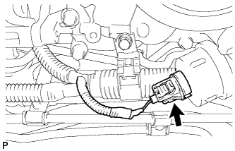
Disconnect the sender gauge connector.
-
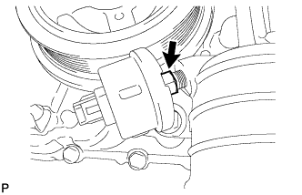
Remove the oil pressure sender gauge.
-
-
REMOVE OIL FILTER BRACKET (w/o Oil Cooler)
-
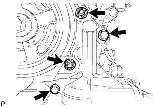
Remove the 2 bolts, 2 nuts and filter bracket.
-
Remove the 2 O-rings.
-
-
DISCONNECT COOLER COMPRESSOR ASSEMBLY (w/ Oil Cooler)
-
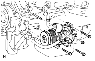
Remove the 3 bolts, nut and stud bolt, and disconnect the cooler compressor.
Tech Tips
It is not necessary to completely remove the compressor. With the hoses connected to the compressor, hang the compressor on the vehicle body with a rope.
-
-
DISCONNECT NO. 2 WATER BY-PASS PIPE SUB-ASSEMBLY (w/ Oil Cooler)
-
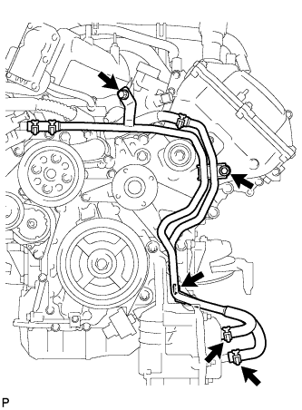
Remove the 3 bolts and disconnect the 2 water by-pass hoses from the oil cooler.
-
-
REMOVE NO. 1 OIL COOLER BRACKET (w/ Oil Cooler)
-
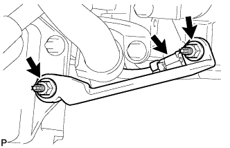
Remove the 2 nuts and bracket.
-
Disconnect the ground wire from the cylinder block.
-
-
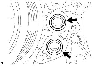
REMOVE OIL FILTER BRACKET (w/ Oil Cooler)
-
Remove the 2 bolts, 2 nuts and filter bracket.
-
Remove the 2 O-rings.
-
-
REMOVE CRANKSHAFT PULLEY
-
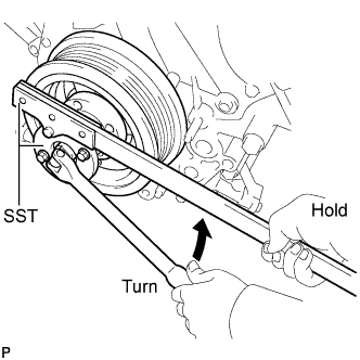
Using SST, loosen the crankshaft pulley set bolt until 2 or 3 threads are engaged.
- SST
- 09213-70011 ( 09213-70020 )
- 09330-00021
-
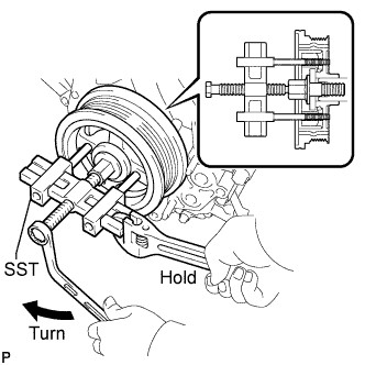
Using the pulley set bolt and SST, remove the crankshaft pulley.
- SST
- 09950-50013 ( 09951-05010, 09952-05010, 09953-05010, 09954-05011 )
-
-
REMOVE CRANKSHAFT TIMING GEAR KEY
-
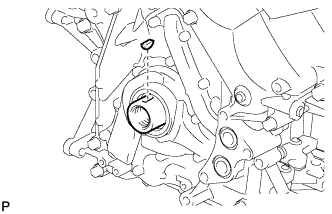
Remove the crankshaft timing gear key from the crankshaft.
-
-
REMOVE FRONT CRANKSHAFT OIL SEAL
-
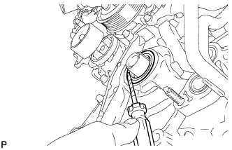
Using a screwdriver, pry out the oil seal.
Tech Tips
Tape the screwdriver tip before use.
Note
Do not damage the surface of the oil seal press fit hole and crankshaft.
-