POWER STEERING OIL PRESSURE SWITCH INSTALLATION

-
INSTALL POWER STEERING OIL PRESSURE SWITCH
-
Install a new O-ring to the oil pressure switch.
-
Apply a light coat of engine oil to the O-ring of the oil pressure switch.
Note
-
When reusing the oil pressure switch, inspect the O-ring.
-
If the O-ring has scratches or cuts, replace the oil pressure switch.
-
-
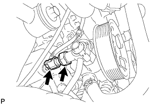
Using a 24 mm deep socket wrench, install the oil pressure switch.
- Torque:
- 21 N*m { 214 kgf*cm, 15 ft.*lbf }
-
Connect the oil pressure switch connector.
-
-
INSTALL FRONT HEIGHT CONTROL SENSOR SUB-ASSEMBLY RH
-
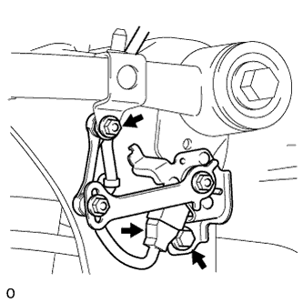
Install the sensor with the bolt and nut.
- Torque:
- for bolt
- 13 N*m { 127 kgf*cm, 9 ft.*lbf }
- for nut
- 5.6 N*m { 57 kgf*cm, 56 in.*lbf }
-
Connect the connector.
-
-
INSTALL FAN AND GENERATOR V BELT
-
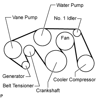
Set the V belt onto every part.
-
While turning the belt tensioner counterclockwise, remove the bar.
Note
Make sure that the V belt is properly set to each pulley.
-
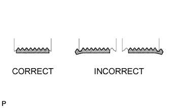
After installing the belt, check that it fits properly in the ribbed grooves.
Tech Tips
Make sure to check by hand that the belt has not slipped out of the grooves on the bottom of the pulley.
-
-
INSTALL AIR CLEANER ASSEMBLY
-
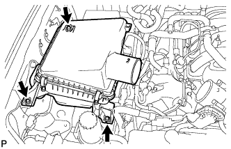
Install the air cleaner with the 3 bolts.
- Torque:
- 5.0 N*m { 51 kgf*cm, 44 in.*lbf }
-
-
INSTALL AIR CLEANER HOSE ASSEMBLY
-
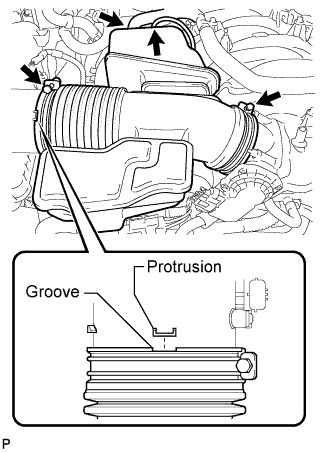
Install the air cleaner hose so that the protrusion of the air cleaner cap aligns with the groove of the hose as shown in the illustration.
-
Tighten the 2 clamps.
- Torque:
- 2.5 N*m { 25 kgf*cm, 22 in.*lbf }
-
Connect the vacuum hose.
-
Connect the No. 2 ventilation hose.
-
-
ADD POWER STEERING FLUID
-
BLEED POWER STEERING FLUID
-
Check the fluid level.
-
Jack up the front of the vehicle and support it with stands.
-
Turn the steering wheel.
-
With the engine stopped, turn the wheel slowly from lock to lock several times.
-
-
Lower the vehicle.
-
Start the engine.
-
Idle the engine for a few minutes.
-
Turn the steering wheel.
-
With the engine idling, turn the wheel left or right to the full lock position and keep it there for 2 to 3 seconds, then turn the wheel to the opposite full lock position and keep it there for 2 to 3 seconds.*1
-
Repeat *1 several times.
Note
For vehicles with VGRS, if the steering wheel is turned from lock to lock repeatedly, the system may stop operating and the amount of rotation before the steering wheel locks may increase due to operation of the overheating prevention function. When the system temperature drops, the system operation automatically returns to normal.
-
-
Stop the engine.
-
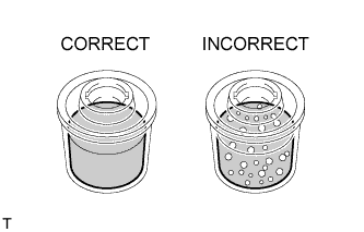
Check for foaming or emulsification.
If the system has to be bled twice because of foaming or emulsification, check for fluid leaks in the system.
-
Check the fluid level.
-
-
INSPECT FOR POWER STEERING FLUID LEAK
-
INSTALL FRONT FENDER APRON SEAL FRONT RH
-
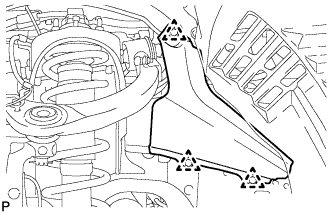
Install the fender apron seal with the 3 clips.
-
-
INSTALL FRONT WHEEL
-
INSTALL NO. 1 ENGINE UNDER COVER SUB-ASSEMBLY
-
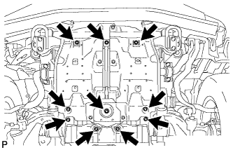
Install the No. 1 engine under cover with the 10 bolts.
- Torque:
- 29 N*m { 296 kgf*cm, 21 ft.*lbf }
-
-
INSTALL FRONT FENDER SPLASH SHIELD SUB-ASSEMBLY LH
-
Push in the clip to install the front fender splash shield sub-assembly LH.
-
Install the 3 bolts and 2 screws.
-
-
INSTALL FRONT FENDER SPLASH SHIELD SUB-ASSEMBLY RH
Tech Tips
Use the same procedure described for the LH side.
-
CONNECT CABLE TO NEGATIVE BATTERY TERMINAL
Note
When disconnecting the cable, some systems need to be initialized after the cable is reconnected Click here.
-
PERFORM VEHICLE HEIGHT OFFSET CALIBRATION
-
Perform the vehicle height offset calibration Click here.
-
-
ADJUST FRONT HEIGHT CONTROL SENSOR LINK SUB-ASSEMBLY
Note
-
Make adjustments from the link that deviates the most from the specified vehicle height value.
-
When the front and rear are at the same level, make adjustments from the front first.
-
If adjustment cannot be completed through the vehicle height offset calibration, adjust the sensor link using the following procedure.
-
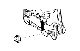
Loosen the nut and adjust the link installation position by moving the height control sensor link up or down in the long hole of the bracket.
Tech Tips
When the link is moved 1 mm (0.0394 in.), the vehicle height changes by approximately 2 mm (0.0787 in.).
-
Tighten the nut of the height control sensor link.
- Torque:
- 5.6 N*m { 57 kgf*cm, 50 in.*lbf }
-
-
PERFORM ZERO POINT CALIBRATION OF G SENSOR
-
Perform the zero point calibration of the G sensor Click here.
-
-
ADJUST HEADLIGHT ASSEMBLY
-
Adjust the headlight Click here.
-
-
INSTALL V-BANK COVER SUB-ASSEMBLY
-
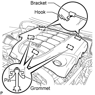
Attach the 2 V-bank cover hooks to the bracket. Then align the 3 V-bank cover grommets with the 3 pins, and press down on the V-bank cover to attach the pins.
-
-
INSTALL UPPER RADIATOR SUPPORT SEAL
-
Install the upper radiator support seal with the 3 clips.
-
-
INSTALL ENGINE ROOM SIDE COVER RH
-
Install the engine room side cover RH with the 7 clips.
-
-
INSTALL ENGINE ROOM SIDE COVER LH
-
Install the engine room side cover LH with the 7 clips.
-