KNOCK SENSOR INSTALLATION

-
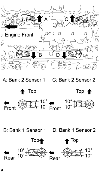
INSTALL KNOCK SENSOR
-
Install the 4 sensors with the 4 bolts so that the sensors are angled as shown in the illustration.
- Torque:
- 20 N*m { 204 kgf*cm, 15 ft.*lbf }
Note
The acceptable installation angle of the sensor is between 10° upward and downward from the horizontal position.
-
Connect the 4 sensor connectors.
-
-
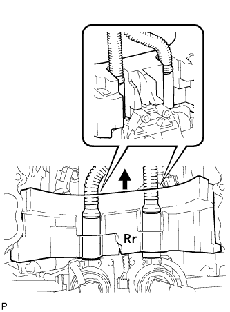
INSTALL NO. 1 ENGINE COVER
Tech Tips
-
Align the No. 1 engine cover cutouts with the air tube.
-
Align the No. 1 engine cover with the air switching valve surface and cylinder head wall.
Note
Make sure that the No. 1 engine cover is flush with the top surface of the intake port of the cylinder head for bank 1 and bank 2.
-
-
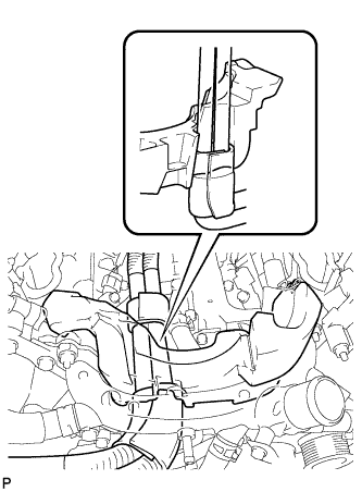
INSTALL NO. 2 ENGINE COVER
Tech Tips
-
Align the No. 2 engine cover cutout with the air tube.
-
Align the No. 2 engine cover with the front water by-pass joint and cylinder head wall.
Note
Make sure that the No. 2 engine cover is flush with the top surface of the intake port of the cylinder head.
-
-
INSTALL INTAKE MANIFOLD
-
Install the intake manifold Click here.
-