ENGINE COOLANT TEMPERATURE SENSOR INSTALLATION

-
INSTALL ENGINE COOLANT TEMPERATURE SENSOR
-
Install a new gasket to the sensor.
-
Using a 19 mm deep socked wrench, install the sensor.
- Torque:
- 20 N*m { 200 kgf*cm, 14 ft.*lbf }
-
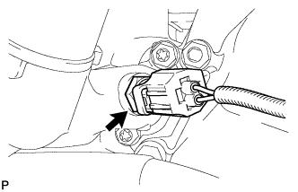
Connect the sensor connector.
-
-
ADD ENGINE COOLANT
-
Add engine coolant.
Standard Capacity Item Specified Condition with transmission oil cooler 16.7 liters (17.6 US qts, 14.7 Imp. qts) without transmission oil cooler 16.2 liters (17.1 US qts, 14.3 Imp. qts) Note
Do not substitute plain water for engine coolant.
Tech Tips
TOYOTA vehicles are filled with TOYOTA SLLC at the factory. In order to avoid damage to the engine cooling system and other technical problems, only use TOYOTA SLLC or similar high quality ethylene glycol based non-silicate, non-amine, non-nitrite, non-borate coolant with long-life hybrid organic acid technology (coolant with long-life hybrid organic acid technology consists of a combination of low phosphates and organic acids).
-
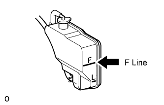
Slowly pour coolant into the radiator reservoir until it reaches the F line.
-
Install the reservoir cap.
-
Press the No. 1 and No. 2 radiator hoses several times by hand, and then check the coolant level. If the coolant level is low, add coolant.
-
Install the radiator cap.
-
Start the engine and warm it up until the thermostat opens.
Note
Switch off the A/C.
-
Maintain the engine speed at 2000 to 2500 rpm.
Note
-
Make sure that the radiator reservoir still has some coolant in it.
-
Pay attention to the needle of the water temperature meter. Make sure that the needle does not show an abnormally high temperature.
-
If there is not enough coolant, the engine may burn out or overheat.
-
Immediately after starting the engine, if the radiator reservoir does not have any coolant, perform the following: 1) stop the engine, 2) wait until the coolant has cooled down, and 3) add coolant until the coolant is filled to the F line.
-
Run the engine at 2000 rpm until the coolant level has stabilized.
-
-
Press the No. 1 and No. 2 radiator hoses several times by hand to bleed air.
CAUTION:
-
Wear protective gloves.
-
Be careful as the radiator hoses are hot.
-
Keep your hands away from the fan.
-
-
Stop the engine, and wait until the engine coolant cools down to ambient temperature.
CAUTION:
Do not remove the radiator cap while the engine and radiator are still hot. Pressurized, hot engine coolant and steam may be released and cause serious burns.
-
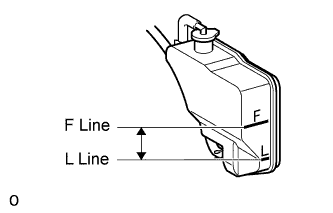
Check that the coolant level is between the F and L lines.
If the coolant level is below the L line, repeat all of the procedures above.
If the coolant level is above the F line, drain coolant so that the coolant level is between the F and L lines.
-
-
INSPECT FOR COOLANT LEAK
-
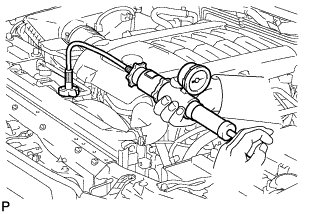
Fill the radiator with coolant and attach a radiator cap tester.
-
Warm up the engine.
-
Using the radiator cap tester, increase the pressure inside the radiator to 123 kPa (1.3 kgf/cm2, 18 psi), and check that the pressure does not drop.
If the pressure drops, check the hoses, radiator and water pump for leaks. If no external leaks are found, check the heater core, cylinder block and head.
-
-
INSTALL V-BANK COVER SUB-ASSEMBLY
-
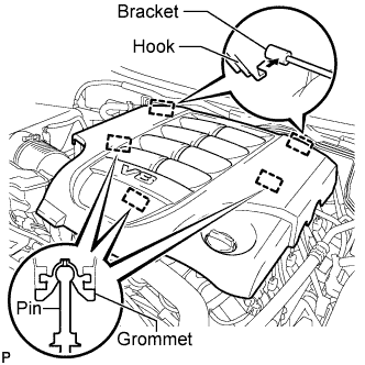
Attach the 2 V-bank cover hooks to the bracket. Then align the 3 V-bank cover grommets with the 3 pins, and press down on the V-bank cover to attach the pins.
-
-
INSTALL UPPER RADIATOR SUPPORT SEAL
-
Install the upper radiator support seal with the 3 clips.
-
-
INSTALL ENGINE ROOM SIDE COVER RH
-
Install the engine room side cover RH with the 7 clips.
-
-
INSTALL ENGINE ROOM SIDE COVER LH
-
Install the engine room side cover LH with the 7 clips.
-
-
INSTALL NO. 1 ENGINE UNDER COVER SUB-ASSEMBLY
-
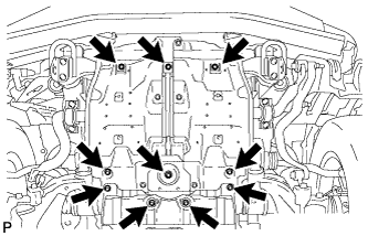
Install the No. 1 engine under cover with the 10 bolts.
- Torque:
- 29 N*m { 296 kgf*cm, 21 ft.*lbf }
-
-
INSTALL FRONT FENDER SPLASH SHIELD SUB-ASSEMBLY LH
-
Push in the clip to install the front fender splash shield sub-assembly LH.
-
Install the 3 bolts and 2 screws.
-
-
INSTALL FRONT FENDER SPLASH SHIELD SUB-ASSEMBLY RH
Tech Tips
Use the same procedure described for the LH side.