CYLINDER HEAD GASKET REMOVAL

-
REMOVE EXHAUST MANIFOLD ASSEMBLY
-
REMOVE CAMSHAFT SUB-ASSEMBLY
-
REMOVE NO. 1 VALVE ROCKER ARM SUB-ASSEMBLY
-
Remove the 32 No. 1 valve rocker arms from the cylinder head.
Tech Tips
Arrange the removed parts in the correct order.
-
-
REMOVE VALVE LASH ADJUSTER ASSEMBLY
-
Remove the 32 valve lash adjusters from the cylinder head.
Tech Tips
Arrange the removed parts in the correct order.
-
-
REMOVE VALVE STEM CAP
-
Remove the 32 valve stem caps from the cylinder head.
Tech Tips
Arrange the removed parts in the correct order.
-
-
REMOVE CYLINDER HEAD SUB-ASSEMBLY LH
-
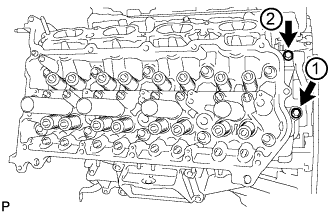
Uniformly loosen and remove the 2 bolts in the sequence shown in the illustration.
-
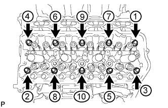
Using a 10 mm bi-hexagon wrench, uniformly loosen the 10 cylinder head bolts in the sequence shown in the illustration. Remove the 10 cylinder head bolts and plate washers.
Note
-
Be careful not to drop washers into the cylinder head.
-
Head warpage or cracking could result from removing bolts in an incorrect order.
Tech Tips
Be sure to arrange the removed parts for each installation position separately.
-
-
Remove the cylinder head LH.
-
-
REMOVE NO. 2 CYLINDER HEAD GASKET
-
REMOVE CYLINDER HEAD SUB-ASSEMBLY
-
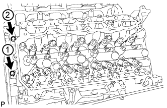
Uniformly loosen and remove the 2 bolts in the sequence shown in the illustration.
-
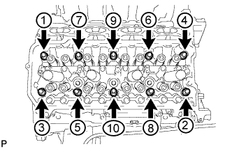
Using a 10 mm bi-hexagon wrench, uniformly loosen the 10 cylinder head bolts in the sequence shown in the illustration. Remove the 10 cylinder head bolts and plate washers.
Note
-
Be careful not to drop washers into the cylinder head.
-
Head warpage or cracking could result from removing bolts in an incorrect order.
Tech Tips
Be sure to arrange the removed parts for each installation position separately.
-
-
Remove the cylinder head.
-
-
REMOVE CYLINDER HEAD GASKET
-
INSPECT CYLINDER HEAD SET BOLT
-
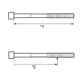
Text in Illustration *1 Measurement Length *2 Distance Using a vernier caliper, measure the length of the cylinder head set bolt from the seat to the end.
Standard length 141.3 to 142.7 mm (5.56 to 5.62 in.) Maximum length 143.7 mm (5.66 in.) If the length is more than the maximum, replace the cylinder head set bolt.
-
Using a vernier caliper, measure the diameter of the elongated threads around the point indicated in the illustration.
Distance Item Specified Condition Intake side bolt 103 mm (4.06 in.) Exhaust side bolt 108 mm (4.25 in.) Standard diameter 10.85 to 11.00 mm (0.427 to 0.433 in.) Minimum diameter 10.60 mm (0.417 in.) If the diameter is less than the minimum, replace the cylinder head set bolt.
Tech Tips
If a visual check reveals no excessively thin areas, check the area of the bolt around the point indicated in the illustration and find the area that has the smallest diameter.
-
-
INSPECT CYLINDER HEAD SUB-ASSEMBLY
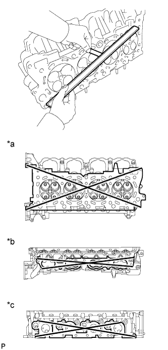
Text in Illustration *a for Cylinder Block Side *b for Intake Manifold Side *c for Exhaust Manifold Side
-
Using a precision straightedge and feeler gauge, measure the warpage of the contact surfaces of the cylinder block and manifold.
Standard Warpage Item Specified Condition Cylinder block side 0.05 mm (0.00197 in.) Intake manifold side 0.08 mm (0.00315 in.) Exhaust manifold side 0.05 mm (0.00197 in.) Maximum warpage 0.10 mm (0.00394 in.) If the warpage is more than the maximum, replace the cylinder head sub-assembly.
-
Using a dye penetrant, check the intake ports, exhaust ports and cylinder head surface for cracks.
If cracked, replace the cylinder head sub-assembly.
-