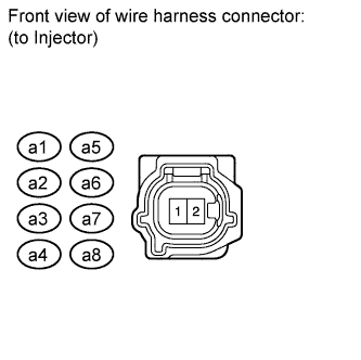
SFI SYSTEM Fuel Injector Circuit
DESCRIPTION
The fuel injectors are located on the intake manifold. They inject fuel into the cylinders based on the signals from the ECM.
WIRING DIAGRAM
Refer to DTC P0300 Click here.
INSPECTION PROCEDURE
Note
Inspect the fuses for circuits related to this system before performing the following inspection procedure.
PROCEDURE
-
CHECK INJECTOR ASSEMBLY (POWER SOURCE)
-
Disconnect the fuel injector connector.
-
Measure the voltage according to the value(s) in the table below.
Standard Voltage Cylinder Tester Connection Switch Condition Specified Condition No. 1 a5-2 - Body ground Engine switch on (IG) 11 to 14 V No. 2 a1-2 - Body ground Engine switch on (IG) 11 to 14 V No. 3 a6-2 - Body ground Engine switch on (IG) 11 to 14 V No. 4 a2-2 - Body ground Engine switch on (IG) 11 to 14 V No. 5 a7-2 - Body ground Engine switch on (IG) 11 to 14 V No. 6 a3-2 - Body ground Engine switch on (IG) 11 to 14 V No. 7 a8-2 - Body ground Engine switch on (IG) 11 to 14 V No. 8 a4-2 - Body ground Engine switch on (IG) 11 to 14 V
NG 
INSPECT INTEGRATION RELAY (IG2) Click here
OK 
-
-
INSPECT FUEL INJECTOR ASSEMBLY
-
Inspect the fuel injector Click here.
NG 
REPLACE FUEL INJECTOR ASSEMBLY Click here
OK
-
-
CHECK HARNESS AND CONNECTOR (FUEL INJECTOR ASSEMBLY - ECM)
-
Disconnect the fuel injector connector.
-
Disconnect the ECM connector.
-
Measure the resistance according to the value(s) in the table below.
Standard Resistance for LHD Cylinder Tester Connection Condition Specified Condition No. 1 a5-1 - Body ground Always 10 kΩ or higher a5-1 - C53-86 (#10) Always Below 1 Ω No. 2 a1-1 - Body ground Always 10 kΩ or higher a1-1 - C53-109 (#20) Always Below 1 Ω No. 3 a6-1 - Body ground Always 10 kΩ or higher a6-1 - C53-85 (#30) Always Below 1 Ω No. 4 a2-1 - Body ground Always 10 kΩ or higher a2-1 - C53-108 (#40) Always Below 1 Ω No. 5 a7-1 - Body ground Always 10 kΩ or higher a7-1 - C53-84 (#50) Always Below 1 Ω No. 6 a3-1 - Body ground Always 10 kΩ or higher a3-1 - C53-107 (#60) Always Below 1 Ω No. 7 a8-1 - Body ground Always 10 kΩ or higher a8-1 - C53-83 (#70) Always Below 1 Ω No. 8 a4-1 - Body ground Always 10 kΩ or higher a4-1 - C53-106 (#80) Always Below 1 Ω for RHD Cylinder Tester Connection Condition Specified Condition No. 1 a5-1 - Body ground Always 10 kΩ or higher a5-1 - C54-86 (#10) Always Below 1 Ω No. 2 a1-1 - Body ground Always 10 kΩ or higher a1-1 - C54-109 (#20) Always Below 1 Ω No. 3 a6-1 - Body ground Always 10 kΩ or higher a6-1 - C54-85 (#30) Always Below 1 Ω No. 4 a2-1 - Body ground Always 10 kΩ or higher a2-1 - C54-108 (#40) Always Below 1 Ω No. 5 a7-1 - Body ground Always 10 kΩ or higher a7-1 - C54-84 (#50) Always Below 1 Ω No. 6 a3-1 - Body ground Always 10 kΩ or higher a3-1 - C54-107 (#60) Always Below 1 Ω No. 7 a8-1 - Body ground Always 10 kΩ or higher a8-1 - C54-83 (#70) Always Below 1 Ω No. 8 a4-1 - Body ground Always 10 kΩ or higher a4-1 - C54-106 (#80) Always Below 1 Ω
NG
REPAIR OR REPLACE HARNESS OR CONNECTOR
OK 
REPLACE ECM Click here
-
-
INSPECT INTEGRATION RELAY (IG2)
-
Inspect the integration relay (IG2) Click here.
NG
REPLACE INTEGRATION RELAY
OK
REPAIR OR REPLACE HARNESS OR CONNECTOR (INTEGRATION RELAY - FUEL INJECTOR ASSEMBLY)
-