SFI SYSTEM, Diagnostic DTC:P2A00, P2A03

| DTC Code | DTC Name |
|---|---|
| P2A00 | A/F Sensor Circuit Slow Response (Bank 1 Sensor 1) |
| P2A03 | A/F Sensor Circuit Slow Response (Bank 2 Sensor 1) |
DESCRIPTION
Refer to DTC P2195 Click here.
| DTC Code | DTC Detection Condition | Trouble Area |
|---|---|---|
| P2A00 | The calculated value of the Air Fuel ratio (A/F) sensor response rate deterioration level is less than the threshold (2 trip detection logic). |
|
| P2A03 | The calculated value of the Air Fuel ratio (A/F) sensor response rate deterioration level is less than the threshold (2 trip detection logic). |
|
MONITOR DESCRIPTION
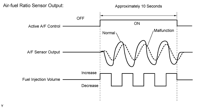
After the engine is warmed up, the ECM performs air-fuel ratio feedback control to maintain the air-fuel ratio at the stoichiometric level. In addition, active A/F control is performed for approximately 10 seconds after the preconditions are met in order to measure the A/F sensor response rate. During active A/F control, the ECM forcibly increases and decreases the injection volume a certain amount, based on the stoichiometric air-fuel ratio learned during normal air-fuel ratio control, and measures the A/F sensor response rate. The ECM receives a signal from the A/F sensor while performing active A/F control and uses it to calculate the A/F sensor response rate deterioration level.
If the A/F sensor response rate deterioration level is less than the threshold, the ECM interprets this as a malfunction and stores DTC(s).
CONFIRMATION DRIVING PATTERN
Tech Tips
Performing this confirmation pattern will activate the air fuel ratio sensor response monitor.
-
Connect the intelligent tester to the DLC3.
-
Turn the engine switch on (IG).
-
Turn the tester on.
-
Clear DTCs (even if no DTCs are stored, perform the clear DTC operation).
-
Turn the engine switch off and wait for at least 30 seconds.
-
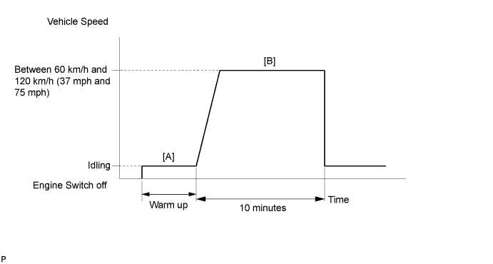
Start the engine and warn it up (until the engine coolant temperature 75°C (167°F)). [A]
-
Turn the tester on.
-
Drive the vehicle at a constant speed of between 60 km/h and 120 km/h (37 mph and 75 mph) for 10 minutes. [B]
CAUTION:
When performing the confirmation driving pattern, obey all speed limits and traffic laws.
-
Enter the following menus: Powertrain / Engine and ECT / DTC / Pending.
-
Read the pending DTC.
-
If a pending DTC is output, the system is malfunctioning.
Tech Tips
If a pending DTC is not output, perform the following procedure.
-
Enter the following menus: Powertrain / Engine and ECT / Utility / All Readiness.
-
Input the DTC P2A00 or P2A03.
-
Check the DTC judgment result.
Intelligent Tester Tester Display Description NORMAL
-
DTC judgment completed
-
System normal
ABNORMAL
-
DTC judgment completed
-
System abnormal
INCOMPLETE
-
DTC judgment not completed
-
Perform driving pattern after confirming DTC enabling conditions
UNKNOWN
-
Unable to perform DTC judgment
-
Number of DTCs which do not fulfill DTC preconditions has reached ECU's memory limit
Tech Tips
-
If the judgment result shows ABNORMAL, the system has a malfunction.
-
If the judgment result shows INCOMPLETE or UNKNOWN, perform step [B] and check the DTC judgment result again.
-
WIRING DIAGRAM
Refer to DTC P2195 Click here.
INSPECTION PROCEDURE
Tech Tips
-
DTC P2A00 and P2A03 are for Euro-OBD only.
-
Malfunctioning areas can be identified by performing the Control the Injection Volume function provided in the Active Test. The Control the Injection Volume function can help to determine whether the air fuel ratio sensor, heated oxygen sensor and other potential trouble areas are malfunctioning.
-
The following instructions describe how to conduct the Control the Injection Volume operation using the intelligent tester.
-
Connect the intelligent tester to the DLC3.
-
Start the engine and turn the tester on.
-
Warm up the engine and run the engine at an engine speed of 2500 rpm for approximately 90 seconds.
-
Enter the following menus: Powertrain / Engine and ECT / Active Test / Control the Injection Volume.
-
Perform the Active Test operation with the engine idling.
-
Monitor the output voltages of the air fuel ratio and heated oxygen sensors (AFS Voltage B1S1 and O2S B1S2 or AFS Voltage B2S1 and O2S B2S2) displayed on the tester.
Tech Tips
-
Change the fuel injection volume within the range of -12% to +12%. The injection volume can be changed in fine gradations.
-
Each sensor reacts in accordance with increases and decreases in the fuel injection volume.
| Tester Display (Sensor) |
Injection Volume | Status | Voltage |
|---|---|---|---|
| AFS Voltage B1S1 or AFS Voltage B2S1 (Air fuel ratio) |
+12% | Rich | Below 3.1 V |
| AFS Voltage B1S1 or AFS Voltage B2S1 (Air fuel ratio) |
-12% | Lean | Higher than 3.4 V |
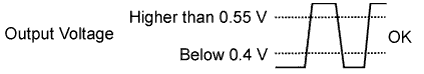
| O2S B1S2 or O2S B2S2 (Heated oxygen) |
+12% | Rich | Higher than 0.55 V |
| O2S B1S2 or O2S B2S2 (Heated oxygen) |
-12% | Lean | Below 0.4 V |
Note
The air fuel ratio sensor has an output delay of a few seconds and the heated oxygen sensor has a maximum output delay of approximately 20 seconds.
| Case | Air Fuel Ratio Sensor (Sensor 1) Output Voltage | Heated Oxygen Sensor (Sensor 2) Output Voltage | Main Suspected Trouble Area |
|---|---|---|---|
| 1 | 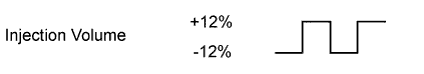 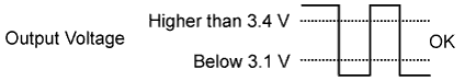 |
 |
- |
| 2 | 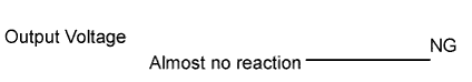 |
|
|
| 3 | |
|
|
| 4 | |
|
|
-
Following the Control the Injection Volume procedure enables technicians to check and graph the voltage outputs of both the air fuel ratio and heated oxygen sensors.
-
To display the graph, enter the following menus: Powertrain / Engine and ECT / Active Test / Control the Injection Volume / All Data / AFS Voltage B1S1 and O2S B1S2 or AFS Voltage B2S1 and O2S B2S2; then press the view button.
Tech Tips
-
Sensor 1 refers to the sensor mounted in front of the Three-Way Catalytic Converter (TWC) and located near the engine assembly.
-
DTC P2A00 indicates malfunctions related to the bank 1 A/F sensor.
-
DTC P2A03 indicates malfunctions related to the bank 2 A/F sensor.
-
Bank 1 refers to the bank that includes the No. 1 cylinder.
-
Bank 2 refers to the bank that includes the No. 2 cylinder.
-
DTC P2A00 or P2A03 may be stored when the air-fuel ratio is stuck rich or lean.
-
A low A/F sensor voltage could be caused by a rich air-fuel mixture. Check for conditions that would cause the engine to run rich.
-
A high A/F sensor voltage could be caused by a lean air-fuel mixture. Check for conditions that would cause the engine to run lean.
-
Read freeze frame data using the intelligent tester. Freeze frame data records the engine condition when malfunctions are detected. When troubleshooting, freeze frame data can help determine if the vehicle was moving or stationary, if the engine was warmed up or not, if the air-fuel ratio was lean or rich, and other data from the time the malfunction occurred.
PROCEDURE
-
CHECK ANY OTHER DTCS OUTPUT (IN ADDITION TO DTC P2A00 AND/OR P2A03)
-
Connect the intelligent tester to the DLC3.
-
Turn the engine switch on (IG).
-
Turn the tester on.
-
Enter the following menus: Powertrain / Engine and ECT / DTC.
-
Read DTCs.
Result Result Proceed to P2A00 and/or P2A03 are output A P2A00 and/or P2A03 and other DTCs are output B Tech Tips
If any DTCs relating to the A/F sensor (DTCs for the A/F sensor heater or A/F sensor admittance) are output, troubleshoot those DTCs first.
B 
GO TO DTC CHART Click here
A 
-
-
INSPECT AIR FUEL RATIO SENSOR (HEATER RESISTANCE)
-
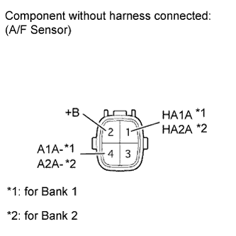
Disconnect the Air Fuel ratio (A/F) sensor connector.
-
Measure the resistance according to the value(s) in the table below.
Standard Resistance Tester Connection Condition Specified Condition 1 (HA1A) - 2 (+B) 20°C (68°F) 1.8 to 3.4 Ω 1 (HA1A) - 4 (A1A-) Always 10 kΩ or higher 1 (HA2A) - 2 (+B) 20°C (68°F) 1.8 to 3.4 Ω 1 (HA2A) - 4 (A2A-) Always 10 kΩ or higher
NG
REPLACE AIR FUEL RATIO SENSOR Click here
OK
-
-
CHECK HARNESS AND CONNECTOR (ECM - AIR FUEL RATIO SENSOR)
-
Disconnect the Air Fuel ratio (A/F) sensor connector.
-
Measure the voltage according to the value(s) in the table below.
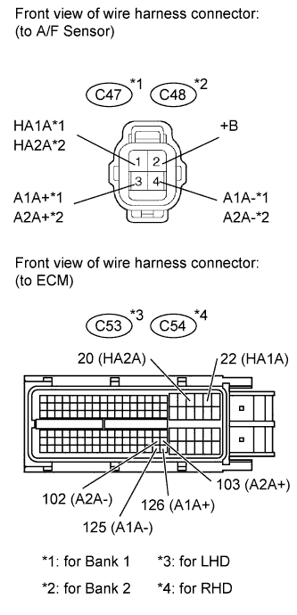
Standard Voltage Tester Connection Switch Condition Specified Condition C47-2 (+B) - Body ground Engine switch on (IG) 11 to 14 V C48-2 (+B) - Body ground Engine switch on (IG) 11 to 14 V -
Turn the engine switch off.
-
Disconnect the ECM connector.
-
Measure the resistance according to the value(s) in the table below.
Standard Resistance for LHD Tester Connection Condition Specified Condition C47-1 (HA1A) - C53-22 (HA1A) Always Below 1 Ω C47-3 (A1A+) - C53-126 (A1A+) Always Below 1 Ω C47-4 (A1A-) - C53-125 (A1A-) Always Below 1 Ω C48-1 (HA2A) - C53-20 (HA2A) Always Below 1 Ω C48-3 (A2A+) - C53-103 (A2A+) Always Below 1 Ω C48-4 (A2A-) - C53-102 (A2A-) Always Below 1 Ω C47-1 (HA1A) or C53-22 (HA1A) - Body ground Always 10 kΩ or higher C47-3 (A1A+) or C53-126 (A1A+) - Body ground Always 10 kΩ or higher C47-4 (A1A-) or C53-125 (A1A-) - Body ground Always 10 kΩ or higher C48-1 (HA2A) or C53-20 (HA2A) - Body ground Always 10 kΩ or higher C48-3 (A2A+) or C53-103 (A2A+) - Body ground Always 10 kΩ or higher C48-4 (A2A-) or C53-102 (A2A-) - Body ground Always 10 kΩ or higher for RHD Tester Connection Condition Specified Condition C47-1 (HA1A) - C54-22 (HA1A) Always Below 1 Ω C47-3 (A1A+) - C54-126 (A1A+) Always Below 1 Ω C47-4 (A1A-) - C54-125 (A1A-) Always Below 1 Ω C48-1 (HA2A) - C54-20 (HA2A) Always Below 1 Ω C48-3 (A2A+) - C54-103 (A2A+) Always Below 1 Ω C48-4 (A2A-) - C54-102 (A2A-) Always Below 1 Ω C47-1 (HA1A) or C54-22 (HA1A) - Body ground Always 10 kΩ or higher C47-3 (A1A+) or C54-126 (A1A+) - Body ground Always 10 kΩ or higher C47-4 (A1A-) or C54-125 (A1A-) - Body ground Always 10 kΩ or higher C48-1 (HA2A) or C54-20 (HA2A) - Body ground Always 10 kΩ or higher C48-3 (A2A+) or C54-103 (A2A+) - Body ground Always 10 kΩ or higher C48-4 (A2A-) or C54-102 (A2A-) - Body ground Always 10 kΩ or higher 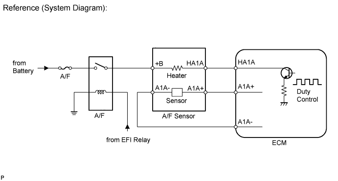
NG
REPAIR OR REPLACE HARNESS OR CONNECTOR
OK
-
-
PERFORM CONFIRMATION DRIVING PATTERN
NEXT
-
CHECK WHETHER DTC OUTPUT RECURS (DTC P2A00 AND/OR P2A03)
-
Connect the intelligent tester to the DLC3.
-
Turn the engine switch on (IG) and turn the tester on.
-
Enter the following menus: Powertrain / Engine and ECT / DTC / Pending.
-
Read pending DTCs.
Result Result Proceed to P2A00 and/or P2A03 is output A No DTC is output B
B
CHECK FOR INTERMITTENT PROBLEMS Click here
A
-
-
REPLACE AIR FUEL RATIO SENSOR
-
Replace the air fuel ratio sensor Click here.
NEXT
-
-
PERFORM CONFIRMATION DRIVING PATTERN
NEXT
-
CHECK WHETHER DTC OUTPUT RECURS (DTC P2A00 AND/OR P2A03)
-
Connect the intelligent tester to the DLC3.
-
Turn the engine switch on (IG) and turn the tester on.
-
Enter the following menus: Powertrain / Engine and ECT / DTC / Pending.
-
Read pending DTCs.
Result Result Proceed to No DTC is output A P2A00 and/or P2A03 are output B
B
REPLACE ECM Click here
A 
END
-