CAMSHAFT OIL CONTROL VALVE INSTALLATION

-
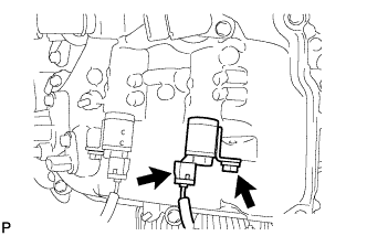
INSTALL CAMSHAFT TIMING OIL CONTROL VALVE ASSEMBLY (for Exhaust Side of Bank 1)
-
Install a new O-ring to the oil control valve.
-
Apply a light coat of engine oil to the O-ring.
-
Install the oil control valve with the bolt.
- Torque:
- 10 N*m { 102 kgf*cm, 7 ft.*lbf }
Note
-
Do not allow foreign matter to contact the oil seal face of the oil control valve (connecting surface with cylinder head cover).
-
Be careful that the O-ring is not cracked or moved out of place when installing the oil control valve.
-
Connect the oil control valve connector.
-
-
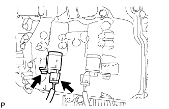
INSTALL CAMSHAFT TIMING OIL CONTROL VALVE ASSEMBLY (for Intake Side of Bank 1)
-
Install a new O-ring to the oil control valve.
-
Apply a light coat of engine oil to the O-ring.
-
Install the oil control valve with the bolt.
- Torque:
- 10 N*m { 102 kgf*cm, 7 ft.*lbf }
Note
-
Do not allow foreign matter to contact the oil seal face of the oil control valve (connecting surface with cylinder head cover).
-
Be careful that the O-ring is not cracked or moved out of place when installing the oil control valve.
-
Connect the oil control valve connector.
-
-
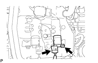
INSTALL CAMSHAFT TIMING OIL CONTROL VALVE ASSEMBLY (for Intake Side of Bank 2)
-
Install a new O-ring to the oil control valve.
-
Apply a light coat of engine oil to the O-ring.
-
Install the oil control valve with the bolt.
- Torque:
- 10 N*m { 102 kgf*cm, 7 ft.*lbf }
Note
-
Do not allow foreign matter to contact the oil seal face of the oil control valve (connecting surface with cylinder head cover).
-
Be careful that the O-ring is not cracked or moved out of place when installing the oil control valve.
-
Connect the oil control valve connector.
-
-
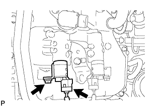
INSTALL CAMSHAFT TIMING OIL CONTROL VALVE ASSEMBLY (for Exhaust Side of Bank 2)
-
Install a new O-ring to the oil control valve.
-
Apply a light coat of engine oil to the O-ring.
-
Install the oil control valve with the bolt.
- Torque:
- 10 N*m { 102 kgf*cm, 7 ft.*lbf }
Note
-
Do not allow foreign matter to contact the oil seal face of the oil control valve (connecting surface with cylinder head cover).
-
Be careful that the O-ring is not cracked or moved out of place when installing the oil control valve.
-
Connect the oil control valve connector.
-
-
INSTALL AIR CLEANER HOSE ASSEMBLY
-
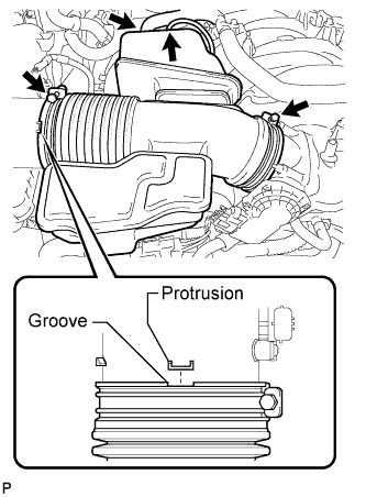
Install the air cleaner hose so that the protrusion of the air cleaner cap aligns with the groove of the hose as shown in the illustration.
-
Tighten the 2 clamps.
- Torque:
- 5.0 N*m { 51 kgf*cm, 44 in.*lbf }
-
Connect the vacuum hose.
-
Connect the No. 2 ventilation hose.
-
-
INSTALL V-BANK COVER SUB-ASSEMBLY
-
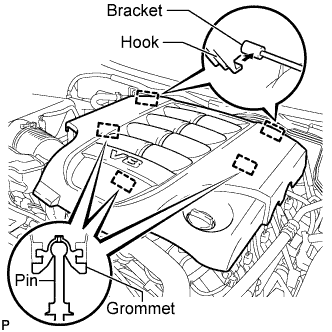
Attach the 2 V-bank cover hooks to the bracket. Then align the 3 V-bank cover grommets with the 3 pins, and press down on the V-bank cover to attach the pins.
-
-
INSTALL UPPER RADIATOR SUPPORT SEAL
-
Install the upper radiator support seal with the 3 clips.
-
-
INSTALL ENGINE ROOM SIDE COVER RH
-
Install the engine room side cover RH with the 7 clips.
-
-
INSTALL ENGINE ROOM SIDE COVER LH
-
Install the engine room side cover LH with the 7 clips.
-