SFI SYSTEM, Diagnostic DTC:P1340, P1342, P1343

| DTC Code | DTC Name |
|---|---|
| P1340 | Camshaft Position Sensor "A" (Bank 1 Sensor 2) |
| P1342 | Camshaft Position Sensor "A" Low Input (MRE) |
| P1343 | Camshaft Position Sensor "A" High Input (MRE) |
DESCRIPTION
The camshaft position sensor (G signal) consists of a magnet and MRE (Magnetic Resistance Element).
The camshaft drive gear (LH) has 3 teeth on its inner circumstance. When the camshaft gear rotates, air gap changes between the protrusion on the teeth and the MRE. The change affects the magnetic field and results in changes in the resistance of the MRE.
The crankshaft position sensor plate has 34 teeth and is installed to the rear end of the crankshaft. The crankshaft position sensor generates 34 signals with every revolution. The ECM detects the standard crankshaft angle based on the G signal, and the actual crankshaft angle and engine speed by the NE signal.
| DTC Code | DTC Detection Condition | Trouble Area |
|---|---|---|
| P1340 | No camshaft position sensor signal is sent to the ECM during cranking (2 trip detection logic). |
|
| No camshaft position sensor signal is sent to the ECM with an engine speed of 600 rpm or more. | ||
| P1342 | The output voltage of the camshaft position sensor is below 0.3 V for 4 seconds (1 trip detection logic). | |
| P1343 | The output voltage of the camshaft position sensor is higher than 4.7 V for 4 seconds (1 trip detection logic). |
MONITOR DESCRIPTION
The camshaft position sensor (G signal) consists of a magnet and MRE.
The camshaft drive gear has 3 teeth on its inner circumference. When the camshaft gear rotates, air gap changes between the protrusion on the gear and the MRE. The change affects the magnetic field and results in changes in the resistance of the MRE. The crankshaft position sensor plate has 34 teeth and outputs 34 signals with every revolution. The ECM detects the standard crankshaft angle based on the G signal, and the actual crankshaft angle and engine speed by the NE signal.
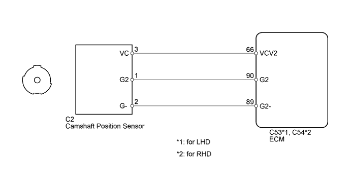
WIRING DIAGRAM
INSPECTION PROCEDURE
Tech Tips
Read freeze frame data using the intelligent tester. Freeze frame data records the engine conditions when malfunctions are detected. When troubleshooting, freeze frame data can help determine if the vehicle was running or stopped, if the engine was warmed up or not, if the air fuel ratio was lean or rich, and other data from the time the malfunction occurred.
PROCEDURE
-
INSPECT CAMSHAFT POSITION SENSOR (SENSOR POWER SOURCE)
-
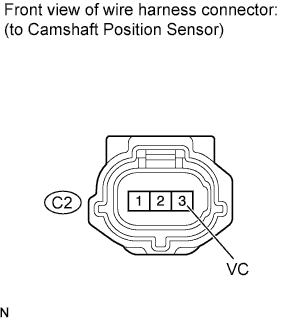
Disconnect the C2 camshaft position sensor connector.
-
Measure the voltage according to the value(s) in the table below.
Standard Voltage Tester Connection Switch Condition Specified Condition C2-3 (VC) - Body ground Engine switch on (IG) 4.5 to 5.0 V
NG 
REPAIR OR REPLACE HARNESS OR CONNECTOR
OK 
-
-
CHECK HARNESS AND CONNECTOR (ECM - CAMSHAFT POSITION SENSOR)
-
Disconnect the C2 camshaft position sensor connector.
-
Disconnect the C53 or C54 ECM connector.
-
Measure the resistance according to the value(s) in the table below.
Standard Resistance for LHD Tester Connection Condition Specified Condition C2-1 (G2) - C53-90 (G2) Always Below 1 Ω C2-2 (G-) - C53-89 (G2-) Always Below 1 Ω C2-1 (G2) or C53-90 (G2) - Body ground Always 10 kΩ or higher C2-2 (G-) or C53-89 (G2-) - Body ground Always 10 kΩ or higher for RHD Tester Connection Condition Specified Condition C2-1 (G2) - C54-90 (G2) Always Below 1 Ω C2-2 (G-) - C54-89 (G2-) Always Below 1 Ω C2-1 (G2) or C54-90 (G2) - Body ground Always 10 kΩ or higher C2-2 (G-) or C54-89 (G2-) - Body ground Always 10 kΩ or higher
NG
REPAIR OR REPLACE HARNESS OR CONNECTOR
OK
-
-
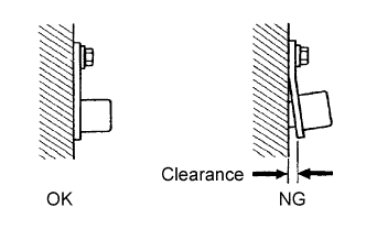
INSPECT SENSOR INSTALLATION
-
Check the camshaft position sensor installation.
OK The camshaft position sensor is installed properly.
NG
SECURELY REINSTALL SENSOR Click here
OK
-
-
INSPECT CAMSHAFT TIMING PLATE (SIGNAL PLATE TOOTH)
-
Check the teeth of the signal plate.
OK Sensor plate teeth do not have any cracks or deformation.
NG
REPLACE CAMSHAFT TIMING PLATE Click here
OK
-
-
REPLACE CAMSHAFT POSITION SENSOR
-
Replace the camshaft position sensor Click here.
NEXT
-
-
CONFIRM WHETHER DTC OUTPUT RECURS
-
Connect the intelligent tester to the DLC3.
-
Turn the engine switch on (IG).
-
Turn the tester on.
-
Clear DTCs Click here.
-
Start the engine.
-
Enter the following menus: Powertrain / Engine and ECT / DTC.
-
Read DTCs.
Result Result Proceed to No DTC is output A P1340, P1342 and/or P1343 are output B Tech Tips
If the engine does not start, replace the ECM.
B
REPLACE ECM Click here
A 
END
-