SFI SYSTEM, Diagnostic DTC:P0136, P0137, P0138, P0156, P0157, P0158

| DTC Code | DTC Name |
|---|---|
| P0136 | Oxygen Sensor Circuit Malfunction (Bank 1 Sensor 2) |
| P0137 | Oxygen Sensor Circuit Low Voltage (Bank 1 Sensor 2) |
| P0138 | Oxygen Sensor Circuit High Voltage (Bank 1 Sensor 2) |
| P0156 | Oxygen Sensor Circuit Malfunction (Bank 2 Sensor 2) |
| P0157 | Oxygen Sensor Circuit Low Voltage (Bank 2 Sensor 2) |
| P0158 | Oxygen Sensor Circuit High Voltage (Bank 2 Sensor 2) |
DESCRIPTION
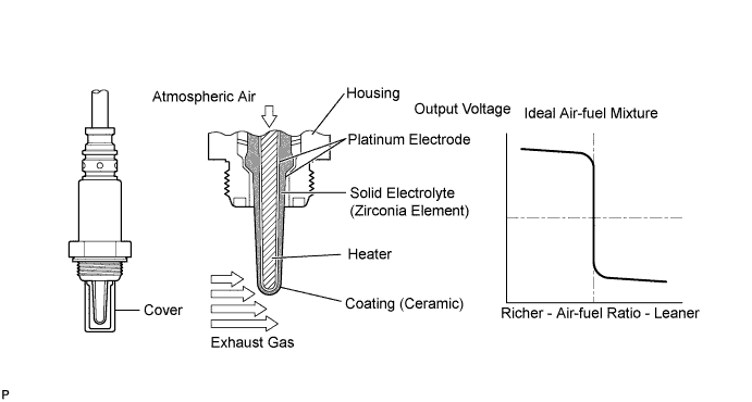
In order to obtain a high purification rate of the carbon monoxide (CO), hydrocarbon (HC) and nitrogen oxide (NOx) components in the exhaust gas, a TWC is used. For the most efficient use of the TWC, the air-fuel ratio must be precisely controlled so that it is always close to the stoichiometric air-fuel ratio. For the purpose of helping the ECM to deliver accurate air-fuel ratio control, a Heated Oxygen (HO2) sensor is used.
The HO2 sensor is located behind the TWC, and detects the oxygen concentration in the exhaust gas. Since the sensor is integrated with the heater that heats the sensing portion, it is possible to detect the oxygen concentration even when the intake air volume is low (the exhaust gas temperature is low).
When the air-fuel ratio becomes lean, the oxygen concentration in the exhaust gas is rich. The HO2 sensor informs the ECM that the post-TWC air-fuel ratio is lean (low voltage, i.e. below 0.45 V).
Conversely, when the air-fuel ratio is richer than the stoichiometric air-fuel ratio, the oxygen concentration in the exhaust gas becomes lean. The HO2 sensor informs the ECM that the post-TWC air-fuel ratio is rich (high voltage, i.e. higher than 0.45 V). The HO2 sensor has the property of changing its output voltage drastically when the air-fuel ratio is close to the stoichiometric level.
The ECM uses the supplementary information from the HO2 sensor to determine whether the air-fuel ratio after the TWC is rich or lean, and adjusts the fuel injection time accordingly. Thus, if the HO2 sensor is working improperly due to internal malfunctions, the ECM is unable to compensate for deviations in the primary air-fuel ratio control.
| DTC Code | DTC Detection Condition | Trouble Area |
|---|---|---|
| P0136* P0156* |
|
|
| P0137 P0157 |
|
|
| P0138* P0158* |
|
|
Tech Tips
*: DTC P0136, P0138, P0156 and P0158 are for Euro-OBD only.
MONITOR DESCRIPTION
Active Air-Fuel Ratio ControlThe ECM usually performs air-fuel ratio feedback control so that the Air Fuel ratio (A/F) sensor output indicates a near stoichiometric air-fuel ratio. This vehicle includes active air-fuel ratio control in addition to regular air-fuel ratio control. The ECM performs active air-fuel ratio control to detect any deterioration in the Three-Way Catalytic Converter (TWC) and Heated Oxygen (HO2) sensor malfunctions (refer to the diagram below).
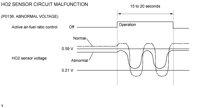
Active air-fuel ratio control is performed for approximately 15 to 20 seconds while driving with a warm engine. During active air-fuel ratio control, the air-fuel ratio is forcibly regulated to become lean or rich by the ECM. If the ECM detects a malfunction, a DTC is stored.
Abnormal Voltage Output of HO2 Sensor (DTC P0136 and P0156)While the ECM is performing active air-fuel ratio control, the air-fuel ratio is forcibly regulated to become rich or lean. If the sensor is not functioning properly, the voltage output variation is small. For example, when the HO2 sensor voltage does not decrease to below 0.21 V and does not increase to higher than 0.59 V during active air-fuel ratio control, the ECM determines that the sensor voltage output is abnormal and stores DTC P0136 or P0156.
During active air-fuel ratio control, the ECM calculates the Oxygen Storage Capacity (OSC)* of the Three-Way Catalytic Converter (TWC) by forcibly regulating the air-fuel ratio to become rich or lean. If the HO2 sensor has an open or short, or the voltage output of the sensor decreases significantly, the OSC indicates an extraordinarily high value. Even if the ECM attempts to continue regulating the air-fuel ratio to become rich or lean, the HO2 sensor output does not change.
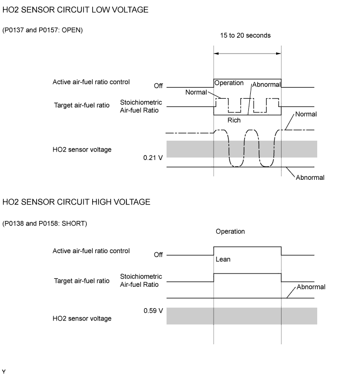
While performing active air-fuel ratio control, when the target air-fuel ratio is rich and the HO2 sensor voltage output is 0.21 V or less (lean), the ECM interprets this as an abnormally low sensor output voltage and stores DTC P0137 or P0157. When the target air-fuel ratio is lean and the voltage output is 0.59 V or higher (rich) during active air-fuel ratio control, the ECM determines that the sensor voltage output is abnormally high, and stores DTC P0138 or P0158.
*: The TWC has the capability to store oxygen. The OSC and the emission purification capacity of the TWC are mutually related. The ECM determines whether the catalyst has deteriorated based on the calculated OSC value Click here.
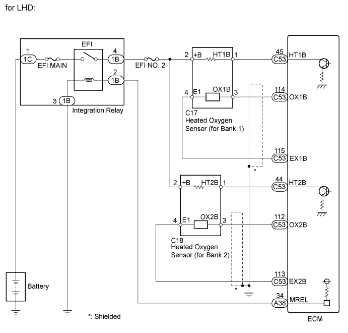
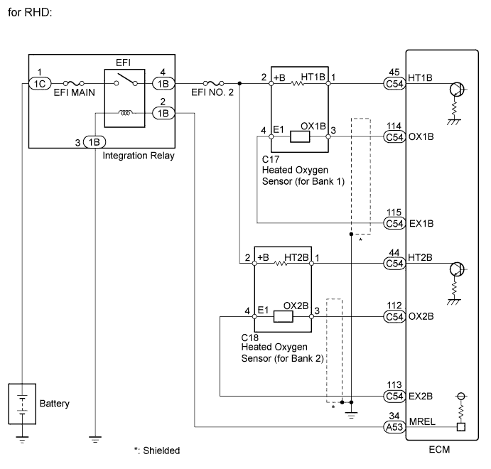
WIRING DIAGRAM
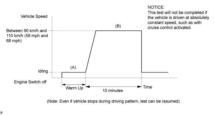
CONFIRMATION DRIVING PATTERN
Tech Tips
-
This confirmation driving pattern is used in the "Perform Confirmation Driving Pattern" procedure of the following diagnostic troubleshooting procedure.
-
Performing this confirmation driving pattern will activate the Heated Oxygen (HO2) sensor monitor (the catalyst monitor is performed simultaneously). This is very useful for verifying the completion of a repair.
Note
This test will not be completed if the vehicle is driven under absolutely constant speed conditions such as with cruise control activated.
-
Connect the intelligent tester to the DLC3.
-
Turn the engine switch on (IG).
-
Turn the tester on.
-
Enter the following menus: Powertrain / Engine and ECT / DTC / Clear.
-
Clear DTCs.
-
Switch the ECM from normal mode to check mode
-
Enter the following menus: Powertrain / Engine and ECT / Data List / O2S (A/FS) Monitor.
-
Check that the item O2S (A/FS) Monitor displays Incmpl (Incomplete).
-
Start the engine and warm it up. (Proceed to "A")
-
Drive the vehicle at between 90 km/h and 110 km/h (56 mph and 68 mph) for at least 10 minutes. (Proceed to "B")
-
Note the state of the Data List items. Those items will change to Compl (Complete) as the O2 Sensor monitor operates.
-
On the tester, enter the following menus: Powertrain / Engine and ECT / DTC / Pending and check if any DTCs (any pending DTCs) are output.
INSPECTION PROCEDURE
Tech Tips
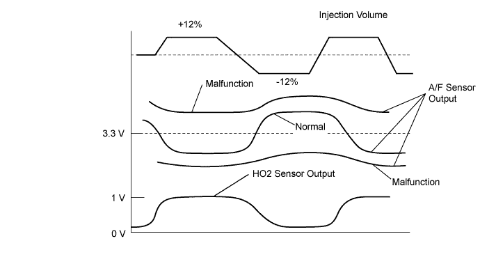
Malfunctioning areas can be identified by performing the Control the Injection Volume function provided in the Active Test. The Control the Injection Volume function can help to determine whether the air fuel ratio sensor, heated oxygen sensor and other potential trouble areas are malfunctioning.
The following instructions describe how to conduct the Control the Injection Volume operation using the intelligent tester.
-
Connect the intelligent tester to the DLC3.
-
Start the engine and turn the tester on.
-
Warm up the engine and run the engine at an engine speed of 2500 rpm for approximately 90 seconds.
-
Enter the following menus: Powertrain / Engine and ECT / Active Test / Control the Injection Volume.
-
Perform the Active Test operation with the engine idling.
-
Monitor the output voltages of the air fuel ratio and heated oxygen sensors (AFS Voltage B1S1 and O2S B1S2 or AFS Voltage B2S1 and O2S B2S2) displayed on the tester.
Tech Tips
-
Change the fuel injection volume within the range of -12% to +12%. The injection volume can be changed in fine gradations.
-
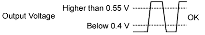
Each sensor reacts in accordance with increases and decreases in the fuel injection volume.
| Tester Display (Sensor) |
Injection Volume | Status | Voltage |
|---|---|---|---|
| AFS Voltage B1S1 or AFS Voltage B2S1 (Air fuel ratio) |
+12% | Rich | Below 3.1 V |
| AFS Voltage B1S1 or AFS Voltage B2S1 (Air fuel ratio) |
-12% | Lean | Higher than 3.4 V |
| O2S B1S2 or O2S B2S2 (Heated oxygen) |
+12% | Rich | Higher than 0.55 V |
| O2S B1S2 or O2S B2S2 (Heated oxygen) |
-12% | Lean | Below 0.4 V |
Note
The air fuel ratio sensor has an output delay of a few seconds and the heated oxygen sensor has a maximum output delay of approximately 20 seconds.
| Case | Air Fuel Ratio Sensor (Sensor 1) Output Voltage | Heated Oxygen Sensor (Sensor 2) Output Voltage | Main Suspected Trouble Area |
|---|---|---|---|
| 1 | 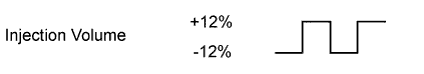 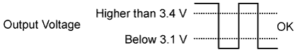 |
 |
- |
| 2 | 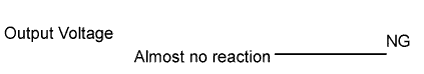 |
|
|
| 3 | |
|
|
| 4 | |
|
|
-
Following the Control the Injection Volume procedure enables technicians to check and graph the voltage outputs of both the air fuel ratio and heated oxygen sensors.
-
To display the graph, enter the following menus: Powertrain / Engine and ECT / Active Test / Control the Injection Volume / All Data / AFS Voltage B1S1 and O2S B1S2 or AFS Voltage B2S1 and O2S B2S2; then press the view button.
Tech Tips
-
DTC P0136, P0138, P0156 and P0158 are for Euro-OBD only.
-
Read freeze frame data using the intelligent tester. Freeze frame data records the engine condition when malfunctions are detected. When troubleshooting, freeze frame data can help determine if the vehicle was moving or stationary, if the engine was warmed up or not, if the air-fuel ratio was lean or rich, and other data from the time the malfunction occurred.
-
If the OX1B wire from the ECM connector is short-circuited to the +B wire, DTC P0136 will be stored.
-
If the OX2B wire from the ECM connector is short-circuited to the +B wire, DTC P0156 will be stored.
PROCEDURE
-
READ OUTPUT DTC
-
Connect the intelligent tester to the DLC3.
-
Turn the engine switch on (IG) and turn the tester on.
-
Enter the following menus: Powertrain / Engine and ECT / DTC.
-
Read DTCs.
Result Result Proceed to P0138 or P0158 is output A P0137 or P0157 is output B P0136 or P0156 is output C P0136, P0137, P0138, P0156, P0157 or P0158 and other DTCs are output D
B 
CHECK FOR EXHAUST GAS LEAKAGE Click here
C
READ VALUE USING INTELLIGENT TESTER (OUTPUT VOLTAGE OF HEATED OXYGEN SENSOR) Click here
D 
GO TO DTC CHART Click here
A 
-
-
READ VALUE USING INTELLIGENT TESTER (OUTPUT VOLTAGE OF HEATED OXYGEN SENSOR)
-
Connect the intelligent tester to the DLC3.
-
Turn the engine switch on (IG) and turn the tester on.
-
Enter the following menus: Powertrain / Engine and ECT / Data List / All Data / O2S B1S2 or O2S B2S2.
-
Allow the engine to idle.
-
Read the Heated Oxygen (HO2) sensor output voltage while idling.
Standard voltage Below 1.0 V
OK
CHECK AIR FUEL RATIO SENSOR Click here
NG
CHECK HEATED OXYGEN SENSOR Click here
-
-
CHECK HEATED OXYGEN SENSOR
-
Disconnect the HO2 sensor connector.
-
Measure the resistance according to the value(s) in the table below.
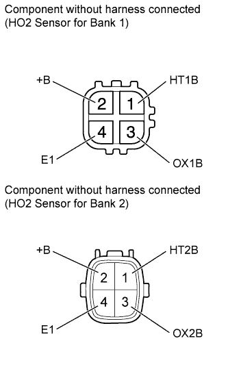
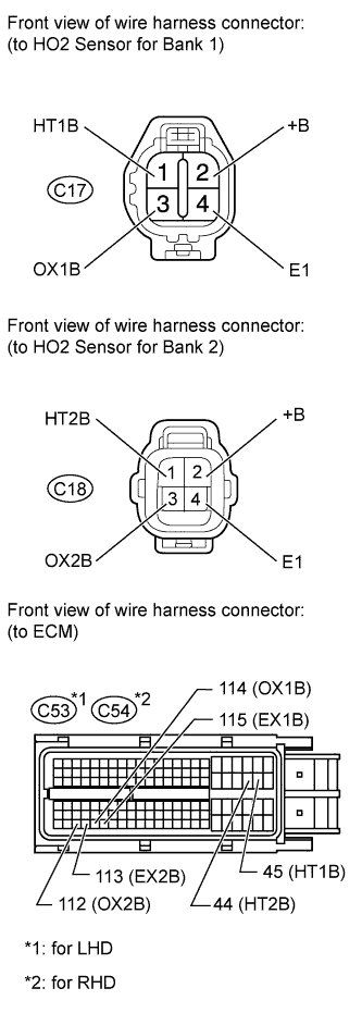
Standard Resistance Tester Connection Condition Specified Condition 2 (+B) - 3 (OX1B) Always 10 kΩ or higher 2 (+B) - 4 (E1) Always 10 kΩ or higher 2 (+B) - 3 (OX2B) Always 10 kΩ or higher 2 (+B) - 4 (E1) Always 10 kΩ or higher
NG
REPLACE HEATED OXYGEN SENSOR Click here
OK
-
-
CHECK HARNESS AND CONNECTOR (HEATED OXYGEN SENSOR - ECM)
-
Turn the engine switch off and wait for 5 minutes.
-
Disconnect the ECM connector.
-
Measure the resistance according to the value(s) in the table below.
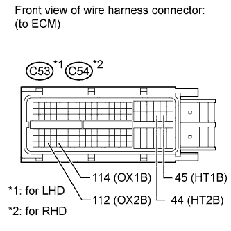
Standard Resistance for LHD Tester Connection Condition Specified Condition C53-45 (HT1B) - C53-114 (OX1B) Always 10 kΩ or higher C53-44 (HT2B) - C53-112 (OX2B) Always 10 kΩ or higher for RHD Tester Connection Condition Specified Condition C54-45 (HT1B) - C54-114 (OX1B) Always 10 kΩ or higher C54-44 (HT2B) - C54-112 (OX2B) Always 10 kΩ or higher
NG
REPAIR OR REPLACE HARNESS OR CONNECTOR
OK 
REPLACE ECM Click here
-
-
CHECK AIR FUEL RATIO SENSOR
Tech Tips
This Air Fuel ratio (A/F) sensor test is to check the A/F sensor current during the fuel cut. When the sensor is normal, the sensor current will indicate below 3 mA in this test.
-
Clear DTC Click here.
-
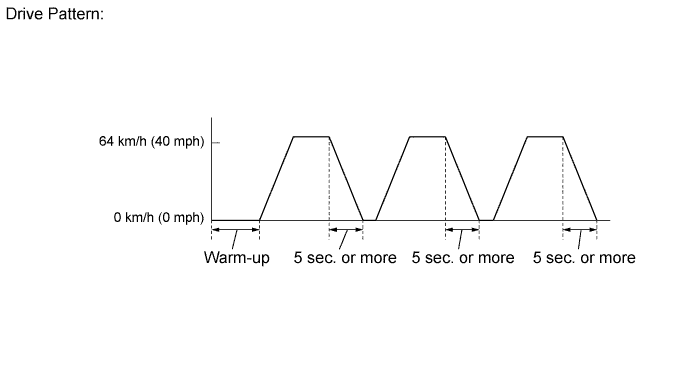
Drive the vehicle by the drive pattern as listed below:
-
Warm up the engine.
-
Drive the vehicle at 60 km/h (40 mph) or more for 10 minutes or more.
-
Stop the vehicle.
-
Accelerator the vehicle until 60 km/h (40 mph) or more and decelerate for 5 seconds or more. Perform this 3 times.
-
-
Enter the following menus: Powertrain / Engine and ECT / Data List / All Data / AFS Current B1S1 and AFS Current B2S1.
-
Read the value of the A/F sensor current while the fuel-cut operation is being performed.
Standard current Below 3.0 mA Note
Do not turn the engine switch off during this step because the test results will be lost.
OK
REPLACE HEATED OXYGEN SENSOR Click here
NG
REPLACE AIR FUEL RATIO SENSOR Click here
-
-
READ VALUE USING INTELLIGENT TESTER (OUTPUT VOLTAGE OF HEATED OXYGEN SENSOR)
-
Connect the intelligent tester to the DLC3.
-
Turn the engine switch on (IG) and turn the tester on.
-
Start the engine.
-
Enter the following menus: Powertrain / Engine and ECT / Data List / All Data / O2S B1S2 or O2S B2S2.
-
After warming up the engine, run the engine at an engine speed of 2500 rpm for 3 minutes.
-
Read the output voltage of the HO2 sensor when the engine speed is suddenly increased.
Tech Tips
Quickly accelerate the engine to 4000 rpm 3 times using the accelerator pedal.
Standard voltage Fluctuates between 0.4 V or less and 0.55 V or higher.
NG
CHECK FOR EXHAUST GAS LEAKAGE Click here
OK
-
-
PERFORM ACTIVE TEST USING INTELLIGENT TESTER (INJECTION VOLUME)
-
Connect the intelligent tester to the DLC3.
-
Start the engine and turn the tester on.
-
Warm up the engine.
-
Enter the following menus: Powertrain / Engine and ECT / Active Test / Control the Injection Volume.
-
Change the fuel injection volume using the tester, and monitor the voltage output of Air Fuel ratio (A/F) and HO2 sensors displayed on the tester.
Tech Tips
-
Change the fuel injection volume within the range of -12% and +12%. The injection volume can be changed in 1% graduations within the range.
-
The A/F sensor is displayed as AFS Voltage B1S1 or AFS Voltage B2S1, and the HO2 sensor is displayed as O2S B1S2 or O2S B2S2 on the tester.
Result Display Item (Sensor) Voltage Variation Proceed to AFS Voltage B1S1 (A/F)
AFS Voltage B2S1 (A/F)
Alternates between higher than and below 3.3 V OK Remains at higher than 3.3 V NG Remains at below 3.3 V NG Tech Tips
A normal HO2 sensor voltage (O2S B1S2 or O2S B2S2) reacts in accordance with increases and decreases in fuel injection volumes. When the A/F sensor voltage remains at either less or higher than 3.3 V despite the HO2 sensor indicating a normal reaction, the A/F sensor is malfunctioning.
-
NG
REPLACE AIR FUEL RATIO SENSOR Click here
OK
-
-
CHECK FOR EXHAUST GAS LEAK
-
Check for exhaust gas leakage.
OK No gas leakage.
NG
REPAIR OR REPLACE EXHAUST GAS LEAK POINT
OK
-
-
CHECK FUEL PRESSURE
-
Check the fuel pressure Click here.
NG
REPAIR OR REPLACE FUEL SYSTEM
OK
-
-
INSPECT FUEL INJECTOR (INJECTION AND VOLUME)
-
Check the injection volume Click here.
NG
REPLACE FUEL INJECTOR Click here
OK
-
-
INSPECT MASS AIR FLOW METER
-
Inspect the mass air flow meter Click here.
NG
REPLACE MASS AIR FLOW METER Click here
OK
-
-
INSPECT ENGINE COOLANT TEMPERATURE SENSOR
-
Inspect the engine coolant temperature sensor Click here.
NG
REPLACE ENGINE COOLANT TEMPERATURE SENSOR Click here
OK
-
-
INSPECT PCV HOSE
-
Check the PCV hose connections Click here.
OK PCV hose is connected correctly and is not damaged.
NG
REPAIR OR REPLACE PCV HOSE Click here
OK
-
-
CHECK AIR INDUCTION SYSTEM
-
Check the air induction system for vacuum leakage Click here.
OK No leakage from air induction system.
NG
REPAIR OR REPLACE AIR INDUCTION SYSTEM Click here
OK
-
-
CHECK SPARKS AND IGNITION
-
Disconnect the injector connectors to prevent the engine from starting.
CAUTION:
Always disconnect all injector connectors.
Note
Do not crank the engine for more than 2 seconds.
-
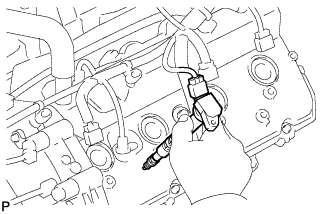
Remove the ignition coil from the cylinder head Click here.
-
Install the spark plug onto the ignition coil.
-
Attach the spark plug assembly to the cylinder head.
-
Crank the engine for less than 2 seconds and check the spark.
OK Sparks jump across electrode gap. -
Install the ignition coil.
-
Reconnect the injector connectors.
NG
REPAIR OR REPLACE IGNITION SYSTEM Click here
OK
REPLACE ECM Click here
-
-
CHECK FOR EXHAUST GAS LEAKAGE
OK No gas leakage.
NG
REPAIR OR REPLACE EXHAUST GAS LEAKAGE POINT
OK
-
INSPECT HEATED OXYGEN SENSOR (HEATER RESISTANCE)
-
Disconnect the heated oxygen (HO2) sensor connector.
-
Measure the resistance according to the value(s) in the table below.
Standard Resistance Tester Connection Condition Specified Condition 1 (HT1B) - 2 (+B) 20°C (68°F) 11 to 16 Ω 1 (HT1B) - 4 (E1) Always 10 kΩ or higher 1 (HT2B) - 2 (+B) 20°C (68°F) 11 to 16 Ω 1 (HT2B) - 4 (E1) Always 10 kΩ or higher
NG
REPLACE HEATED OXYGEN SENSOR Click here
OK
-
-
INSPECT INTEGRATION RELAY (EFI RELAY)
-
Remove the integration relay from the engine room relay block.
-
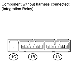
Inspect the EFI MAIN fuse.
-
Remove the EFI MAIN fuse from the integration relay.
-
Measure the resistance according to the value(s) in the table below.
Standard Resistance Tester Connection Condition Specified Condition EFI MAIN fuse Always Below 1 Ω -
Reinstall the EFI MAIN fuse.
-
-
Inspect the EFI relay.
-
Measure the resistance according to the value(s) in the table below.
Standard Resistance Tester Connection Condition Specified Condition 1C-1 - 1B-4 No battery voltage applied to terminals 1B-2 and 1B-3 10 kΩ or higher Battery voltage applied to terminals 1B-2 and 1B-3 Below 1 Ω
-
NG
REPLACE INTEGRATION RELAY
OK
-
-
CHECK HARNESS AND CONNECTOR (HEATED OXYGEN SENSOR - ECM)
-
Disconnect the HO2 sensor connector.
-
Measure the voltage according to the value(s) in the table below.
Standard Voltage Tester Connection Switch Condition Specified Condition C17-2 (+B) - Body ground Engine switch on (IG) 11 to 14 V C18-2 (+B) - Body ground Engine switch on (IG) 11 to 14 V -
Turn the engine switch off.
-
Disconnect the ECM connector.
-
Measure the resistance according to the value(s) in the table below.
Standard Resistance for LHD Tester Connection Condition Specified Condition C17-1 (HT1B) - C53-45 (HT1B) Always Below 1 Ω C17-3 (OX1B) - C53-114 (OX1B) Always Below 1 Ω C17-4 (E1) - C53-115 (EX1B) Always Below 1 Ω C18-1 (HT2B) - C53-44 (HT2B) Always Below 1 Ω C18-3 (OX2B) - C53-112 (OX2B) Always Below 1 Ω C18-4 (E1) - C53-113 (EX2B) Always Below 1 Ω C17-1 (HT1B) or C53-45 (HT1B) - Body ground Always 10 kΩ or higher C17-3 (OX1B) or C53-114 (OX1B) - Body ground Always 10 kΩ or higher C18-1 (HT2B) or C53-44 (HT2B) - Body ground Always 10 kΩ or higher C18-3 (OX2B) or C53-112 (OX2B) - Body ground Always 10 kΩ or higher for RHD Tester Connection Condition Specified Condition C17-1 (HT1B) - C54-45 (HT1B) Always Below 1 Ω C17-3 (OX1B) - C54-114 (OX1B) Always Below 1 Ω C17-4 (E1) - C54-115 (EX1B) Always Below 1 Ω C18-1 (HT2B) - C54-44 (HT2B) Always Below 1 Ω C18-3 (OX2B) - C54-112 (OX2B) Always Below 1 Ω C18-4 (E1) - C54-113 (EX2B) Always Below 1 Ω C17-1 (HT1B) or C54-45 (HT1B) - Body ground Always 10 kΩ or higher C17-3 (OX1B) or C54-114 (OX1B) - Body ground Always 10 kΩ or higher C18-1 (HT2B) or C54-44 (HT2B) - Body ground Always 10 kΩ or higher C18-3 (OX2B) or C54-112 (OX2B) - Body ground Always 10 kΩ or higher 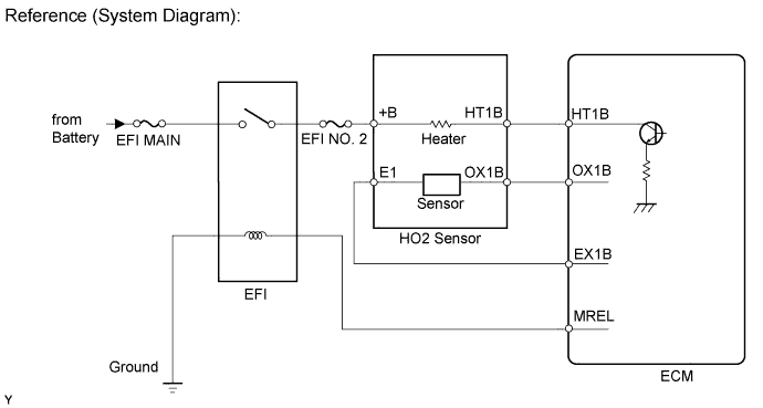
NG
REPAIR OR REPLACE HARNESS OR CONNECTOR
OK
-
-
REPLACE HEATED OXYGEN SENSOR
-
Replace the heated oxygen sensor Click here.
NEXT
-
-
PERFORM CONFIRMATION DRIVING PATTERN
-
Perform Confirmation Driving Pattern.
NEXT
-
-
CHECK WHETHER DTC OUTPUT RECURS (DTC P0136, P0137, P0138, P0156, P0157 OR P0158)
-
Connect the intelligent tester to the DLC3.
-
Turn the engine switch on (IG).
-
Turn the tester on.
-
Enter the following menus: Powertrain / Engine and ECT / Utility / All Readiness.
-
Input DTCs: P0136, P0137, P0138, P0156, P0157 and P0158.
-
Check that DTC monitor is NORMAL. If DTC monitor is INCOMPLETE, perform the drive pattern adding the vehicle speed and using the second gear to decelerate the vehicle.
OK No DTC is output.
NG
REPLACE AIR FUEL RATIO SENSOR Click here
OK
REPAIR COMPLETE
-
-
REPLACE AIR FUEL RATIO SENSOR
-
Replace the air fuel ratio sensor Click here.
NEXT
-
-
PERFORM CONFIRMATION DRIVING PATTERN
-
Perform Confirmation Driving Pattern.
NEXT
-
-
CHECK WHETHER DTC OUTPUT RECURS (DTC P0136, P0137, P0138, P0156, P0157 OR P0158)
-
Connect the intelligent tester to the DLC3.
-
Turn the engine switch on (IG).
-
Turn the tester on.
-
Enter the following menus: Powertrain / Engine and ECT / Utility / All Readiness.
-
Input DTCs: P0136, P0137, P0138, P0156, P0157 and P0158.
-
Check that DTC monitor is NORMAL. If DTC monitor is INCOMPLETE, perform the drive pattern adding the vehicle speed and using the second gear to decelerate the vehicle.
OK No DTC is output.
NG
REPLACE HEATED OXYGEN SENSOR Click here
OK
REPAIR COMPLETE
-