SFI SYSTEM, Diagnostic DTC:P0037, P0038, P0057, P0058, P102D, P105D

| DTC Code | DTC Name |
|---|---|
| P0037 | Oxygen Sensor Heater Control Circuit Low (Bank 1 Sensor 2) |
| P0038 | Oxygen Sensor Heater Control Circuit High (Bank 1 Sensor 2) |
| P0057 | Oxygen Sensor Heater Control Circuit Low (Bank 2 Sensor 2) |
| P0058 | Oxygen Sensor Heater Control Circuit High (Bank 2 Sensor 2) |
| P102D | O2 Sensor Heater Circuit Performance Bank 1 Sensor 2 Stuck ON |
| P105D | O2 Sensor Heater Circuit Performance Bank 2 Sensor 2 Stuck ON |
DESCRIPTION
-
Refer to DTC P0136 Click here.
Tech Tips
-
When any of these DTCs is stored, the ECM enters fail-safe mode. The ECM turns off the Heated Oxygen (HO2) Sensor heater in fail-safe mode. Fail-safe mode continues until the engine switch is turned off.
-
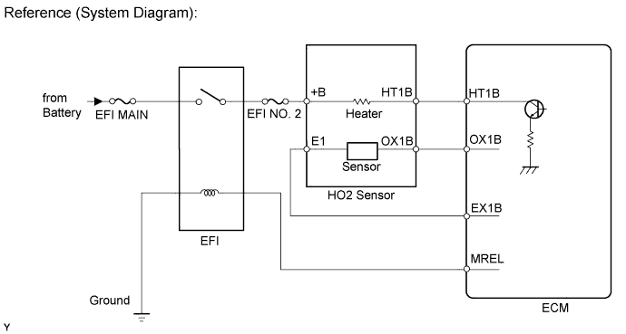
The ECM provides a pulse width modulated control circuit to adjust the current through the heater. The HO2 sensor heater circuit uses a relay on the +B side of the circuit.
| DTC Code | DTC Detection Condition | Trouble Area |
|---|---|---|
| P0037 P0057 |
The Heated Oxygen (HO2) sensor heater current is below 0.3 A (1 trip detection logic). |
|
| P0038 P0058 |
The Heated Oxygen (HO2) sensor heater current is exceeds the specified value (1 trip detection logic). |
|
| P102D P105D |
The heater current is higher than the specified value while the heater is not operating (1 trip detection logic). | ECM |
Tech Tips
-
Bank 1 refers to the bank that includes the No. 1 cylinder.
-
Bank 2 refers to the bank that does not include the No. 1 cylinder.
-
Sensor 1 refers to the sensor closest to the engine assembly.
-
Sensor 2 refers to the sensor farthest away from the engine assembly.
MONITOR DESCRIPTION
The sensing portion of the Heated Oxygen (HO2) sensor has a zirconia element which is used to detect the oxygen concentration in the exhaust gas. If the zirconia element is at the appropriate temperature, and the difference between the oxygen concentrations surrounding the inside and outside surfaces of the sensor is large, the zirconia element generates voltage signals. In order to increase the oxygen concentration detecting capacity of the zirconia element, the ECM supplements the heat from the exhaust with heat from a heating element inside the sensor.
Heated oxygen sensor heater range check (P0037, P0038, P0057, P0058, P102D and P105D):The ECM monitors the current applied to the heated oxygen sensor heater to check the heater for malfunctions. If the heater current is outside the normal range, the signal transmitted by the heated oxygen sensor becomes inaccurate. When the current in the heated oxygen sensor heater is outside the normal operating range, the ECM interprets this as a malfunction in the sensor and stores a DTC.
WIRING DIAGRAM
Refer to DTC P0136 Click here.
CONFIRMATION DRIVING PATTERN
These DTCs are stored when the engine idles for 110 seconds or more.
INSPECTION PROCEDURE
Tech Tips
-
Sensor 2 refers to the sensor mounted behind the Three-Way Catalytic Converter (TWC) and located far from the engine assembly.
-
Read freeze frame data using the intelligent tester. Freeze frame data records the engine condition when malfunctions are detected. When troubleshooting, freeze frame data can help determine if the vehicle was moving or stationary, if the engine was warmed up or not, if the air-fuel ratio was lean or rich, and other data from the time the malfunction occurred.
PROCEDURE
-
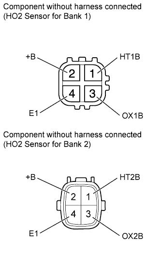
INSPECT HEATED OXYGEN SENSOR (HEATER RESISTANCE)
-
Disconnect the heated oxygen (HO2) sensor connector.
-
Measure the resistance according to the value(s) in the table below.
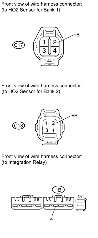
Standard Resistance Tester Connection Condition Specified Condition 1 (HT1B) - 2 (+B) 20°C (68°F) 11 to 16 Ω 1 (HT1B) - 4 (E1) Always 10 kΩ or higher 1 (HT2B) - 2 (+B) 20°C (68°F) 11 to 16 Ω 1 (HT2B) - 4 (E1) Always 10 kΩ or higher
NG 
REPLACE HEATED OXYGEN SENSOR Click here
OK 
-
-
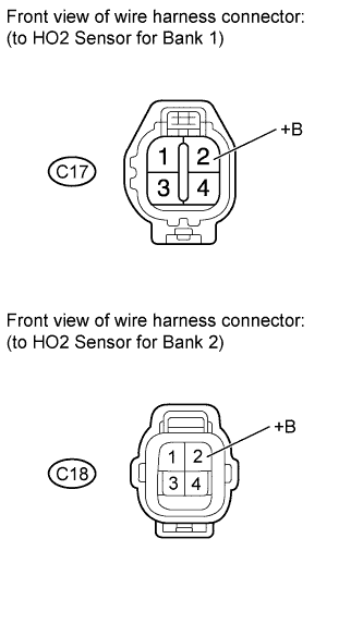
CHECK TERMINAL VOLTAGE (+B OF HO2 SENSOR)
-
Disconnect the HO2 sensor connector.
-
Measure the voltage according to the value(s) in the table below.
Standard Voltage Tester Connection Switch Condition Specified Condition C17-2 (+B) - Body ground Engine switch on (IG) 11 to 14 V C18-2 (+B) - Body ground Engine switch on (IG) 11 to 14 V Result Result Proceed to NG A OK B
B 
CHECK HARNESS AND CONNECTOR (HO2 SENSOR - ECM) Click here
A
-
-
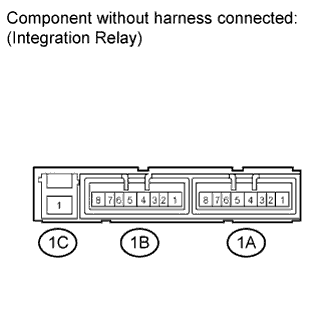
INSPECT INTEGRATION RELAY (EFI)
-
Remove the integration relay from the engine room relay block.
-
Inspect the EFI MAIN fuse.
-
Remove the EFI MAIN fuse from the integration relay.
-
Measure the resistance according to the value(s) in the table below.
Standard Resistance Tester Connection Condition Specified Condition EFI MAIN fuse Always Below 1 Ω -
Reinstall the EFI MAIN fuse.
-
-
Inspect the EFI relay.
-
Measure the resistance according to the value(s) in the table below.
Standard Resistance Tester Connection Condition Specified Condition 1C-1 - 1B-4 No battery voltage applied to terminals 1B-2 and 1B-3 10 kΩ or higher Battery voltage applied to terminals 1B-2 and 1B-3 Below 1 Ω
-
NG
REPLACE INTEGRATION RELAY (EFI)
OK
-
-
CHECK HARNESS AND CONNECTOR (HO2 SENSOR - INTEGRATION RELAY)
-
Check the EFI NO. 2 fuse.
-
Remove the EFI NO. 2 fuse from the engine room relay block.
-
Measure the resistance according to the value(s) in the table below.
Standard Resistance Tester Connection Condition Specified Condition EFI NO. 2 fuse Always Below 1 Ω -
Reinstall the EFI NO. 2 fuse.
-
-
Disconnect the HO2 sensor connector.
-
Remove the integration relay from the engine room relay block.
-
Measure the resistance according to the value(s) in the table below.
Standard Resistance Tester Connection Condition Specified Condition C17-2 (+B) - 1B-4 Always Below 1 Ω C18-2 (+B) - 1B-4 Always Below 1 Ω C17-2 (+B) or 1B-4 - Body ground Always 10 kΩ or higher C18-2 (+B) or 1B-4 - Body ground Always 10 kΩ or higher
NG
REPAIR OR REPLACE HARNESS OR CONNECTOR
OK 
CHECK ECM POWER SOURCE CIRCUIT Click here
-
-
CHECK HARNESS AND CONNECTOR (HO2 SENSOR - ECM)
-
Disconnect the HO2 sensor connector.
-
Disconnect the ECM connector.
-
Measure the resistance according to the value(s) in the table below.
Standard Resistance for LHD Tester Connection Condition Specified Condition C17-1 (HT1B) - C53-45 (HT1B) Always Below 1 Ω C18-1 (HT2B) - C53-44 (HT2B) Always Below 1 Ω C17-1 (HT1B) or C53-45 (HT1B) - Body ground Always 10 kΩ or higher C18-1 (HT2B) or C53-44 (HT2B) - Body ground Always 10 kΩ or higher for RHD Tester Connection Condition Specified Condition C17-1 (HT1B) - C54-45 (HT1B) Always Below 1 Ω C18-1 (HT2B) - C54-44 (HT2B) Always Below 1 Ω C17-1 (HT1B) or C54-45 (HT1B) - Body ground Always 10 kΩ or higher C18-1 (HT2B) or C54-44 (HT2B) - Body ground Always 10 kΩ or higher
NG
REPAIR OR REPLACE HARNESS OR CONNECTOR
OK
-
-
CHECK WHETHER DTC OUTPUT RECURS
-
Connect the intelligent tester to the DLC3.
-
Turn the engine switch on (IG).
-
Turn the tester on.
-
Clear DTCs Click here.
-
Start the engine.
-
Allow the engine to idle for 2 minutes or more.
-
Enter the following menus: Powertrain / Engine and ECT / DTC.
-
Read DTCs.
Result Result Proceed to No DTC is output A P0037, P0038, P0057, P0058, P102D and/or P105D are output B
B
REPLACE ECM Click here
A
CHECK FOR INTERMITTENT PROBLEMS Click here
-