REPAIR INSTRUCTION INITIALIZATION
-
Procedures necessary when cable is disconnected/reconnected to battery terminal
Procedures Necessary when Cable is Disconnected/Reconnected to Battery Terminal Necessary Procedures Procedure Details Effects or Inoperative Functions When Necessary Procedures are not Performed Notes Initialization of steering angle sensor Drive the vehicle on a straight road at 35 km/h (22 mph) or more for 5 seconds or more.
-
VGRS system
-
Other related systems cannot operate properly
- Correction of steering angle neutral point Fully turn the steering wheel to the right and left. Parking guidance function - Servo motors initialization Using the intelligent tester, perform the servo motor initialization. Air conditioning system does not operate properly During initialization, the AUTO indicator light comes on, and then goes off when initialization has finished. Initialization of power back door system Completely close the back door by hand once. Power back door function Initialization is not necessary if the cable is disconnected and reconnected to the negative (-) battery terminal while the back door is closed. However, the power back door system will not operate if the back door is not unlocked after the cable is reconnected. Note
After the engine switch is turned off, the multi-media module receiver assembly records various types of memory and settings. As a result, after turning the engine switch off, make sure to wait for the time specified in the following table before disconnecting the cable from the negative (-) battery terminal.
Waiting Time before Disconnecting Cable from Negative (-) Battery Terminal Condition Waiting Time Vehicle enrolled in G-BOOK system 6 minutes Vehicle not enrolled in G-BOOK system 1 minute -
-
Procedures necessary when ECU or other parts are replaced
Procedures Necessary when ECU or Other Parts are Replaced Replacement Part Necessary Procedures Effects or Inoperative Functions When Necessary Procedures are not Performed Notes for 1UR-FE
ECM
Register VIN DTC P0630 is output - Distance Control ECU Initialization Cannot adjust millimeter wave radar sensor - Millimeter wave radar sensor assembly Adjusting the radar beam axis Dynamic radar cruise control system does not operate normally - Suspension control ECU Vehicle height offset calibration Vehicle height sensor date may be affected due to installation position, or vehicle height recognition may be erroneous After vehicle height offset calibration is performed, it is necessary to calibrate the yaw rate sensor Height control sensor Vehicle height offset calibration Vehicle height sensor date may be affected due to installation position, or vehicle height recognition may be erroneous After vehicle height offset calibration is performed, it is necessary to calibrate the yaw rate sensor
-
Automatic transmission assembly
-
Valve body assembly
-
Any of shift solenoid valves
for 1UR-FE
Perform the Reset Memory (AT initialization) Large shift shock -
-
Automatic transmission assembly
-
Valve body assembly
-
Any of shift solenoid valves
for 3UR-FE
Perform the Reset Memory (AT initialization) Large shift shock - for 3UR-FE
Automatic transmission fluid
ATF thermal degradation estimate reset The value of the Data List item "ATF Thermal Degradation Estimate" is not estimated correctly - Tire pressure warning ECU and receiver
-
Register transmitter IDs
-
Initialize tire pressure warning system.
-
When DTC detection conditions of "transmitter ID not received" DTC is met, tire pressure warning light blinks for 1 minute, and then illuminates
-
Tire pressure monitoring function
- Tire pressure warning valve and transmitter
-
Register transmitter IDs
-
Initialize tire pressure warning system.
-
When DTC detection conditions of "transmitter ID not received" DTC is met, tire pressure warning light blinks for 1 minute, and then illuminates
-
Tire pressure monitoring function
Even if only one wheel is replaced, IDs for all 5 wheels must be registered. Skid Control ECU (Master Cylinder Solenoid) Yaw rate and acceleration sensor zero point calibration.
-
ABS warning light illumination
-
Slip indicator light illumination
- Yaw rate sensor
-
Clearing zero point calibration data.
-
Yaw rate and acceleration sensor zero point calibration.
-
ABS warning light illumination
-
Slip indicator light illumination
-
-
Steering control ECU
-
Steering column
-
Steering intermediate shaft
-
Steering actuator assembly
Calibration
-
VGRS system
-
DTC output
- Steering angle sensor Initialization
-
VGRS system
-
Other related systems cannot operate properly
-
-
Multi-media module receiver assembly *1
-
Telematics transceiver *1
Vehicle contract setting
-
G-BOOK service
-
Emergency call service
-
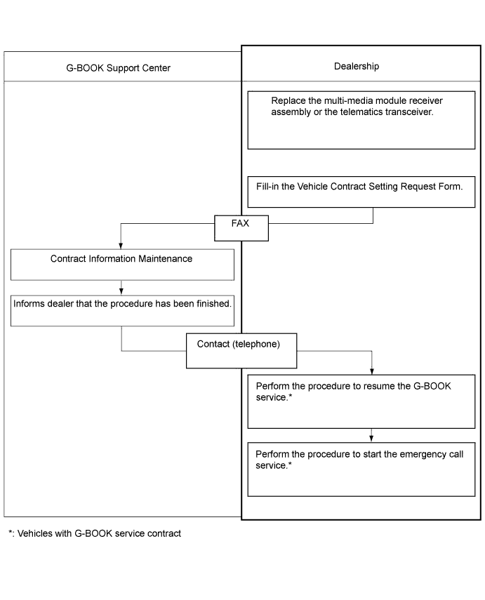
If the multi-media module receiver assembly or telematics transceiver is replaced on vehicles that do not have a contract for the G-BOOK service, perform the vehicle contract setting.
-
If the multi-media module receiver assembly or telematics transceiver is replaced on vehicles that have a contract for the G-BOOK service, perform the vehicle contract setting and the procedure to resume the G-BOOK service and to start the emergency call service.
Rear television camera Rear television camera optional axis (Camera position setting) Vehicle width extension lines and expected course are deviated Replace or installation angle of the rear television camera changes because of the removal and installation of the rear television camera Side television camera Side television camera optional axis (Camera position setting) Vehicle parallel lines and expected course are deviated Replace or installation angle of the side television camera changes because of the removal and installation of the side television camera Parking assist ECU
-
Steering angle neutral point in memory
-
Store the left and right maximum steering angles
-
Rear television camera optical axis (Camera position setting)
-
Side television camera optical axis (Camera position setting)
-
Parking assist monitor system
-
Side monitor system
Replace or installation angle of the rear television camera changes because of the removal and installation of the rear television camera or side television camera
-
ID code box
-
Steering lock ECU
-
ECM
-
Key
-
Certification ECU
Registration
-
Wireless door lock operation
-
Entry operation
-
Engine starting
-
Steering unlock
Refer to the Service Bulletin for the registration method
-
Front Power window regulator motor LH
-
Front Power window regulator motor RH
-
Rear Power window regulator motor LH
-
Rear Power window regulator motor RH
Initialize the motor
-
Jam protection function
-
Power window control system
-
DTC B2313 is output
- Servo motors Servomotors initialization Air conditioning system does not operate properly During initialization, the AUTO indicator light comes on, and then goes off when initialization has finished.
-
Sliding roof drive gear (Sliding roof ECU)
-
Sliding roof glass
Initialize sliding roof system
-
Auto operation
-
Jam protection function
-
Sliding roof operation after engine switch off
-
Wireless door lock control function
-
Key-linked operation function (Driver side door only)
-
Entry lock switch-linked operation
-
-
Power back door unit
-
Back door lock
Initialize power back door system Power back door system -
-
*1: w/ G-BOOK system
-
-
REGISTRATION RELATED TO ECM (for 1UR-FE)
Note
The Vehicle Identification Number (VIN) must be input into a replacement ECM.
Tech Tips
The VIN is a 17-digit alphanumeric vehicle identification number. The GTS is required to register the VIN.
-
DESCRIPTION
Tech Tips
This registration section consists of 2 parts: Read VIN and Write VIN.
-
Read VIN: This process allows the VIN stored in the ECM to be read in order to confirm that the 2 VINs, provided with the vehicle and stored in the vehicle ECM, are the same.
-
Write VIN: This process allows the VIN to be input into the ECM. If the ECM is replaced, or the ECM VIN and vehicle VIN do not match, the VIN can be registered, or overwritten in the ECM by following this procedure.
-
-
READ VIN
-
Confirm the vehicle VIN.
-
Connect the GTS to the DLC3.
-
Turn the engine switch on (IG).
-
Turn the GTS on.
-
Enter the following menus: Powertrain / Engine and ECT / Utility / VIN / VIN Read.
-
-
WRITE VIN
-
Confirm the vehicle VIN.
-
Connect the GTS to the DLC3.
-
Turn the engine switch on (IG).
-
Turn the GTS on.
-
Enter the following menus: Powertrain / Engine and ECT / Utility / VIN / VIN Write.
-
-
-
REGISTRATION SFI SYSTEM (for 1UR-FE)
Note
The Vehicle Identification Number (VIN) must be input into a replacement ECM.
Tech Tips
The VIN is a 17-digit alphanumeric vehicle identification number. The GTS is required to register the VIN.
-
DESCRIPTION (Using the GTS)
Tech Tips
This registration section consists of 2 parts: Read VIN and Write VIN.
-
Read VIN: This process allows the VIN stored in the ECM to be read in order to confirm that the 2 VINs, provided with the vehicle and stored in the vehicle ECM, are the same.
-
Write VIN: This process allows the VIN to be input into the ECM. If the ECM is replaced, or the ECM VIN and vehicle VIN do not match, the VIN can be registered, or overwritten in the ECM by following this procedure.
-
-
READ VIN
-
Confirm the vehicle VIN.
-
Connect the GTS to the DLC3.
-
Turn the engine switch on (IG).
-
Turn the GTS on.
-
Enter the following menus: Powertrain / Engine and ECT / Utility / VIN / VIN Read.
-
-
WRITE VIN
-
Confirm the vehicle VIN.
-
Connect the GTS to the DLC3.
-
Turn the engine switch on (IG).
-
Turn the GTS on.
-
Enter the following menus: Powertrain / Engine and ECT / Utility / VIN / VIN Write.
-
-
-
INITIALIZATION RELATED TO DYNAMIC RADAR CRUISE CONTROL
Note
After removing and installing or replacing the distance control ECU assembly, be sure to perform the following procedures.
INITIALIZE DISTANCE CONTROL ECU
-
Turn the engine switch on (IG).
-
Turn the cruise control main switch on.
-
Depress the brake pedal (brake switch on).
-
With the brake pedal depressed, push the cruise control main switch to +RES 3 times within 3 seconds, and check that the buzzer sounds.
Note
At this time, do not turn the headlight dimmer switch on. Due to the activation of the beam axis automatic adjustment mode, turning the headlight dimmer switch on may result in an incorrect setting. If the headlight dimmer switch is turned on by mistake, perform the beam axis adjustment again.
-
-
ADJUSTMENT MILLIMETER WAVE RADAR SENSOR
-
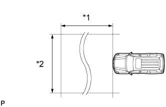
Text in Illustration *1 Approx. 10 m *2 Approx. 14 m ADJUST MILLIMETER WAVE RADAR SENSOR ASSEMBLY
Note
-
Perform measurements on a level surface.
-
Make sure that there are no metal objects on the ground or within a 10 m (32.8 ft.) x 14 m (45.9 ft.) area in front of the vehicle. If possible, the surrounding area should also be free of large metal objects.
-
Before adjusting, perform the following:
-
Remove all cargo from the inside of the vehicle.
-
Adjust the tire pressure to the specified value(s).
-
Adjust the vehicle's height to the standard height.
-
-
Adjust the vertical direction.
-
Remove any dust and oil from the level rack of the millimeter wave radar sensor assembly.
-
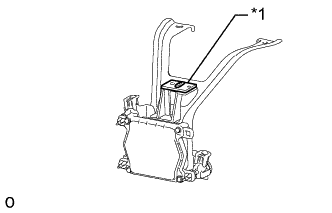
Text in Illustration *1 Level Set a level for use with the sensor in the center of the level rack of the millimeter wave radar sensor assembly.
-
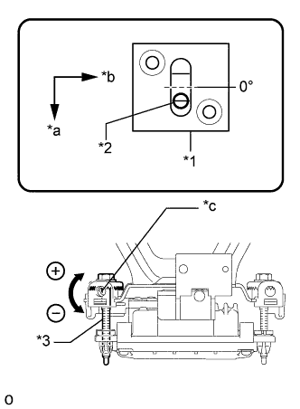
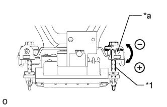
Text in Illustration *1 Level *2 Air Bubble *3 Bolt A *a FR *b LH *c Screwdriver Insertion Hole Using a screwdriver, adjust the sensor by turning the vertical adjusting bolt of the millimeter wave radar sensor assembly (bolt A) until the air bubble is centered on the red line of the level as shown in the illustration.
Standard 0.2° upward Tech Tips
The adjustable range within the red frame of the level is +/-0.2°.
Adjustment Vertical adjustment - Upward direction: Turn bolt A in minus direction
- Downward direction: Turn bolt A in plus direction
For 1 complete turn of screwdriver, sensor moves about 0.12°
-
-

Text in Illustration *1 Millimeter Wave Radar Sensor Adjust SST (reflector) height.
-
Adjust SST (reflector) so that the center of SST (reflector) is the same height as the millimeter wave radar sensor assembly.
- SST
- 09870-60000 (09870-60010), 09870- 60040
-
-
Place SST (reflector).
-
Hang a pointed weight from the center of the front and rear bumpers of the vehicle (center of the emblem) and accurately mark the center points on the ground.
-
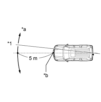
Text in Illustration *1 String *a Adjust Center By Moving String To Right And Left *b Extend String Through Front Center Mark Mark a point 5 m (16.4 ft.) in front of the vehicle on the line that connects the front and rear center point marks.
Tech Tips
Affix one end of a string to the rear center point mark and extend the string 5 m (16.4 ft.) from the front of the vehicle. Move the other end of the string left and right to align the string with the front center point mark and make a straight line.
-
Place SST at a position 12 mm (0.472 in.) from the marked position, to the right of the vehicle.
Note
Perform the operation as precisely as possible.
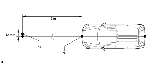
Text in Illustration *a Reflector (SST) Placement Point *b Millimeter Wave Radar Sensor Position
-
-
Adjust the beam axis.
-
Connect the intelligent tester to the DLC3.
-
Turn the engine switch on (IG).
-
Turn the intelligent tester main switch ON, and turn the cruise control main switch ON.
-
Select "Radar Cruise" from the display screen.
Tech Tips
A buzzer will sound for 1 second.
-
Select "Utility" from the display screen.
-
Select "Beam Axis Adjustment" from the display screen.
-
Follow the tester display, and continue with the adjustment.
-
Intelligent tester
Note
-
Turn the cruise control main switch ON before pressing Next.
-
Make sure there is at least 20 cm (7.9 inches) between the radar sensor and any nearby individuals.
-
-
Check the following items on the laser cruise divergence data screen.
CAUTION:
While using the intelligent tester's beam axis adjustment mode, the actual direction and angle of the radar sensor may be different from the intelligent tester's data. In such a case, the deviation is displayed on the combination meter's multi-information display.
-
-
Confirm that the distance value is approximately 5 m (16.41 ft.).
Tech Tips
-
A value between 0.0 and 6.3 m (20.67 ft.) is indicated.
-
If the distance is 0 m (0 ft.), the sensor cannot detect the target. Reconfirm that there is no metal in the specified area in front of the vehicle (refer to the NOTICE at the beginning of this adjustment procedure).
-
-
Confirm that the left/right side value is between 0.0 and 6.3.
Tech Tips
cannot detect the target. Reconfirm that there is no metal in the specified area in front of the vehicle (refer to the NOTICE at the beginning of this adjustment procedure).
-
-
-
Adjust the horizontal direction.
-
Read the current amount of angle deviation.
Standard 0° (Both left and right) -
Text in Illustration *1 Bolt B *a Screwdriver Insertion Hole Based on the results of the beam axis deviation measurement, using a screwdriver, adjust the sensor by turning the horizontal adjusting bolt of the millimeter wave radar sensor assembly (bolt B).
Adjustment Horizontal adjustment - Right direction: Turn bolt B in plus direction
- Left direction: Turn bolt B in minus direction
For 1 complete turn of screwdriver, sensor moves about 0.07° Note
If it is difficult to reach a value of 0°, it is possible that the sensor is targeting an object other than SST. Reconfirm that there are no reflective objects in the surrounding area.
-
Text in Illustration *1 Aluminum foil Because the driving learned value will be reset, cover the left half of the sensor with aluminum foil or equivalent (a metal material that blocks electric waves) for a period of approximately 10 seconds.
Note
At this time, leave SST in place and make sure there are no objects between the right half of the sensor and the reflector.
Tech Tips
When the value is reset, the buzzer will sound for 10 seconds, a distance value between 0 and 6.3° and a right side value between 0 and 6.3 m (20.7 ft.) will be displayed on the screen.
-
Continue the procedure according to the display to complete the beam axis adjustment.
-
Disconnect the intelligent tester from the vehicle.
-
-
Text in Illustration *1 Level Reconfirm the vertical direction.
-
Set a level for use with the sensor in the center of the level rack of the millimeter wave radar sensor assembly.
-
Text in Illustration *1 Level *2 Air Bubble *3 Bolt A *a FR *b LH *c Screwdriver Insertion Hole Using a screwdriver, adjust the sensor by turning the vertical adjusting bolt of the millimeter wave radar sensor assembly (bolt A) until the air bubble is centered on the red line of the level as shown in the illustration.
Standard 0.2° upward Tech Tips
The adjustable range within the red frame of the level is +/-0.2°.
Adjustment Vertical adjustment - Upward direction: Turn bolt A in minus direction
- Downward direction: Turn bolt A in plus direction
For 1 complete turn of screwdriver, sensor moves about 0.12°
-
-
-
DRIVE TEST
-
Perform the drive test.
Note
-
Be sure to perform the driving test after adjusting the millimeter wave radar sensor assembly.
-
Be careful when driving.
-
Drive at 30 km/h (19 mph) on a straight road with good visibility while staying in the center of the lane.
Note
Because the pre-crash safety system may activate under the following conditions, avoid conditions like these when performing the test.
-
There are objects on the side of the road at the beginning of a curve.
-
Passing an oncoming vehicle on a curve.
-
Crossing a narrow metal bridge.
-
There are metal objects on the road surface.
-
There is an oncoming vehicle when turning right.
-
Rapidly approaching a vehicle driving in front.
-
-
On a straight road, when passing an oncoming vehicle with no danger of collision, check that the master warning does not illuminate and that the buzzer does not sound. At the same time, check that "BRAKE!" is not displayed on the display in the combination meter.
-
If "BRAKE!" is displayed, perform the millimeter wave radar sensor assembly adjustment again.
Tech Tips
-
Check the installation condition of the millimeter wave radar sensor assembly.
-
Check that the pre-crash safety brake switch is not pushed in.
-
-
-
-
-
INITIALIZATION RELATED TO AUTOMATIC TRANSMISSION (for 1UR-FE)
-
RESET MEMORY
Note
-
Perform Reset Memory (AT initialization) when replacing the automatic transmission assembly, valve body assembly or any of the shift solenoid valves.
-
Reset Memory can be performed only with the GTS.
Tech Tips
The ECM memorizes the control conditions of the automatic transmission assembly and engine assembly. Therefore, when the automatic transmission assembly, valve body assembly or any of the shift solenoid valves has been replaced, it is necessary to reset the memory so that the ECM can memorize the new information. The reset procedure is as follows.
-
Connect the GTS to the DLC3.
-
Turn the engine switch on (IG).
-
Turn the GTS on.
-
Enter the following menus: Powertrain / Engine and ECT / Utility / Reset Memory.
Note
After performing Reset Memory, be sure to perform the Road Test described earlier.
Tech Tips
The ECM learns through the Road Test.
-
-
-
INITIALIZATION RELATED TO AUTOMATIC TRANSMISSION SYSTEM (for 3UR-FE)
-
RESET MEMORY
Note
-
Perform the Reset Memory (AT initialization) when replacing the automatic transmission assembly, valve body assembly or any of the shift solenoid valves.
-
The Reset Memory can only be performed with the GTS.
Tech Tips
The ECM memorizes the control conditions of the automatic transmission assembly and engine assembly. Therefore, when the automatic transmission assembly, valve body assembly or any of the shift solenoid valves has been replaced, it is necessary to reset the memory so that the ECM can memorize the new information.
-
Connect the GTS to the DLC3.
-
Turn the engine switch on (IG).
-
Turn the GTS on.
-
Enter the following menus: Powertrain / Engine and ECT / Utility / Reset Memory.
Note
After performing the Reset Memory, be sure to perform the Road Test described earlier.
Tech Tips
The ECM learns through the Road Test.
-
-
-
ATF THERMAL DEGRADATION ESTIMATE RESET (for 3UR-FE)
Note
If either of the following conditions is met, perform ATF Thermal Degradation Estimate Reset.
-
The ATF has been replaced.
Tech Tips
If 50000 or more is displayed for the Data List item "ATF Thermal Degradation Estimate", thermal degradation of the ATF is suspected. Perform ATF Thermal Degradation Estimate Reset after replacing the ATF.
-
Approximately 50% or more of the ATF has been replaced during a repair of the transmission or a similar operation.
-
Connect the GTS to the DLC3.
-
Turn the engine switch on (IG).
Note
Do not start the engine.
-
Turn the GTS on.
-
Enter the following menus: Powertrain / Engine and ECT / Utility / ATF Thermal Degradation Estimate Reset.
-
-
REGISTRATION RELATED TO TIRE PRESSURE WARNING
-
Before registration
Note
The transmitter ID is written on the tire pressure warning valve and transmitter. It is not possible to read the transmitter ID after installing the tire to the wheel. Therefore, make a note of the transmitter ID before installing the tire.
-
In case of tire pressure warning ECU and receiver replacement:
-
Read the registered transmitter IDs that are stored in the old ECU using the GTS and note them down.
-
If reading the stored transmitter IDs is impossible due to malfunctions of components such as the tire pressure warning ECU and receiver, remove the tires from the wheels and check the IDs located on the tire pressure warning valve and transmitters.
-
-
In case of tire pressure warning valve and transmitter replacement:
-
Take a note of the 7 digit number (transmitter ID) written on the tire pressure warning valve and transmitter.
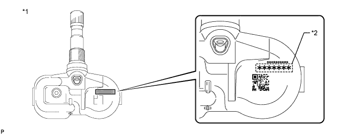
Text in Illustration *1 Tire Pressure Warning Valve and Transmitter *2 Transmitter ID (7 Digit Number) -
-
-
REGISTER TRANSMITTER ID
Tech Tips
-
The previously registered IDs will be cleared from memory when the registration is completed.
-
If the ID registration step is not completed within 300 seconds, ID registration will be canceled.
-
Set the air pressure of all tires to the specified value(s).
-
Turn the engine switch off.
-
Connect the GTS to the DLC3.
-
Turn the engine switch on (IG) and the GTS on.
-
Enter the following menus: Chassis / Tire Pressure Monitor / Utility / ID Registration.
-
Perform the procedure displayed on the GTS.
-
-
CONFIRMATION OF TRANSMITTER ID REGISTRATION
Note
-
It may take up to a few minutes to update the tire pressure data. If the values are not displayed after a few minutes, perform troubleshooting according to the inspection procedure for DTCs C2121/21 to C2125/25.
-
If the IDs have not been registered, DTC C2171/71 is stored in the tire pressure warning ECU and receiver after 3 minutes or more.
-
If normal pressure values are displayed, the IDs have been registered correctly.
-
If the tire pressure values are not displayed after a few minutes, the IDs may be incorrect or the system may have a malfunction.
-
After all IDs are registered, DTC C2126/26 is stored in the tire pressure warning ECU and receiver and the tire pressure warning light blinks for 1 minute and then illuminates. When the tire pressure warning ECU and receiver successfully receives signals from all the transmitters whose IDs are stored in the ECU, DTC C2126/26 is cleared and the tire pressure warning light goes off.
-
Enter the following menus: Chassis / Tire Pressure Monitor / Data List.
-
Read the "ID Tire Inflation Pressure" values.
-
Confirm that the tire pressure data of all tires is displayed on the GTS screen.
-
-
-
INITIALIZATION RELATED TO TIRE PRESSURE WARNING
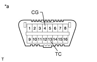
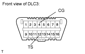
Text in Illustration *a Front view of DLC3 Note
-
Initialization can be confirmed through the tire pressure warning light.
-
The order in which the data is received is random.
-
If the signals from all the wheels are received, initialization is completed.
-
Initialization is completed when the Data List "ID Tire Inflation Pressure" display shows the correct pressures.
-
Initialization is normally completed within a few minutes.
-
It may take up to a few minutes until the values are displayed. If the values are not displayed after a few minutes, perform troubleshooting according to the inspection procedure for DTCs C2121/21 to C2125/25.
-
If initialization has not been completed successfully, DTC C2177/77 is stored after the vehicle is driven at a speed of 37 km/h (23 mph) or more for 20 minutes or more.
-
During test mode (sensor check mode), the system will not change to initialization mode even if the tire pressure warning reset switch is pushed.
-
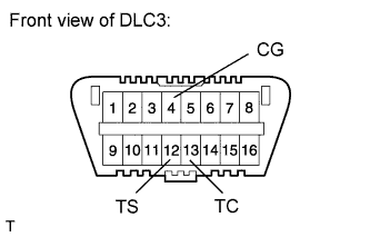
Initialization can be terminated by connecting terminals 13 (TC) and 4 (CG) of the DLC3.
-
BEFORE INITIALIZATION
-
Make sure that the tires are cold.
-
Set the air pressure of all tires to the specified value(s).
-
-
INITIALIZATION PROCEDURE
-
Turn the engine switch on (IG).
-
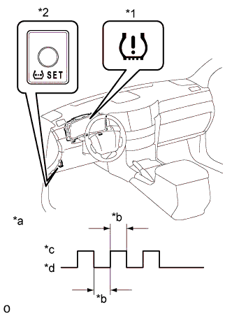
Text in Illustration *1 Tire Pressure Warning Light *2 Tire Pressure Warning Reset Switch *a Tire Pressure Warning Light Output Pattern *b 1 sec. *c ON *d OFF Press and hold the tire pressure warning reset switch for 3 seconds or more so that the tire pressure warning light blinks 3 times.
-
Turn the engine switch off.
-
Connect the GTS to the DLC3.
-
Turn the engine switch on (IG) and turn the GTS on.
-
Enter the following menus: Chassis / Tire Pressure Monitor / Data List.
-
Check that initialization has been completed.
-
Confirm that the tire pressure data of all tires is displayed on the GTS screen.
-
-
-
INITIALIZATION RELATED TO ACTIVE HEIGHT CONTROL SUSPENSION
-
DESCRIPTION
-
If replacing the suspension control ECU and/or height control sensor, perform the vehicle height offset calibration.
-
-
VEHICLE HEIGHT OFFSET CALIBRATION
Note
-
Make sure that the pressure of the tires is normal.
-
Make sure that the vehicle is empty.
-
Make sure that the parking brake is released and that the shift lever is in N.
-
Make sure that the easy access mode switch is off.
-
-
PERFORM VEHICLE HEIGHT INSPECTION
-
Adjust the pressure of the tires.
-
Stabilize the suspension by releasing the parking brake and bouncing the corners of the vehicle up and down.
-
Start the engine.
-
Perform the following operation twice: Set the vehicle height to LO with the height control switch, and then return the vehicle height to NORMAL.
-
Turn the engine switch off.
-
Connect the intelligent tester to the DLC3.
-
Move the shift lever to N and move the vehicle forward and rearward.
-
Turn the engine switch on (IG) and the intelligent tester on.
Tech Tips
Make sure the engine is not running.
-
Check that the vehicle height is NORMAL.
Tech Tips
The N of the multi-information display height control indicator in the combination meter turns on.
-
Perform the vehicle height inspection.
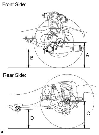
Measuring points A Ground clearance of front wheel center B Ground clearance of the front adjusting cam bolt center C Ground clearance of the rear axle shaft center D Ground clearance of the rear lower control arm front side center Standard Vehicle Height Front (A minus B) Rear (C minus D) 101 mm (3.98 in.) 94 mm (3.70 in.) -
Using a jack, set the vehicle to the standard vehicle height and eliminate any difference in height between the left and right sides of the vehicle.
Note
The vehicle height may be outside the calibration range if there is a difference in height between the left and right sides of the vehicle.
-
Using the intelligent tester, enter the following menus: Chassis / AHC / Data List. Then read and record the values for "After Height Adjust" and "Height Adjust" for each wheel.
AHC Tester Display Measurement Item/Range Normal Condition Diagnosis Note FR Height Adjust Display of vehicle height offset recorded value of front right wheel /
min.: -3276.8 mm (-129 in.)
max.: 3276.7 mm (129 in.)
- - FL Height Adjust Display of vehicle height offset recorded value of front left wheel /
min.: -3276.8 mm (-129 in.)
max.: 3276.7 mm (129 in.)
- - RR Height Adjust Display of vehicle height offset recorded value of rear right wheel /
min.: -3276.8 mm (-129 in.)
max.: 3276.7 mm (129 in.)
- - RL Height Adjust Display of vehicle height offset recorded value of rear left wheel /
min.: -3276.8 mm (-129 in.)
max.: 3276.7 mm (129 in.)
- - FR After Height Adjust Display of after-calibration vehicle height value of front right wheel /
min.: -3276.8 mm (-129 in.)
max.: 3276.7 mm (129 in.)
- - FL After Height Adjust Display of after-calibration vehicle height value of front left wheel /
min.: -3276.8 mm (-129 in.)
max.: 3276.7 mm (129 in.)
- - RR After Height Adjust Display of after-calibration vehicle height value of rear right wheel /
min.: -3276.8 mm (-129 in.)
max.: 3276.7 mm (129 in.)
- - RL After Height Adjust Display of after-calibration vehicle height value of rear left wheel /
min.: -3276.8 mm (-129 in.)
max.: 3276.7 mm (129 in.)
- - -
Turn the engine switch off.
NEXT 
-
-
PERFORM VEHICLE HEIGHT OFFSET CALIBRATION
Note
The possible vehicle height automatic adjustment value is 20 mm (0.787 in.). If the "Height Adjust value + (Standard value - Measurement value - After Height Adjust value)" is 20 mm (0.787 in.) or more, first perform the vehicle height adjustment for the front side, and for the rear side.
-
Turn the engine switch off.
-
Connect the intelligent tester to the DLC3.
-
Turn the engine switch on (IG) and the intelligent tester on.
-
Enter the following menus: Chassis / AHC / Utility / Height offset.
-
For each wheel, follow the instructions on the intelligent tester screen and input the input value to complete the vehicle height offset calibration.
Tech Tips
Input value = Measurement value and standard value
-
Remove the jack.
-
Start the engine.
-
Set the vehicle height to LO and check that LO of the multi-information display height control indicator stops blinking and illuminates.
-
Set the vehicle height to NORMAL and check that N of the height control indicator stops blinking and illuminates.
-
Turn the engine switch off.
-
Perform the vehicle height inspection. Check that the result is within +/-8 mm (+/-0.315 in.) of the standard value.
-
Perform yaw rate and G sensor zero point calibration.
NEXT
END
-
-
-
CALIBRATION RELATED TO VEHICLE STABILITY CONTROL
-
DESCRIPTION
-
After replacing VSC-related components, clearing and reading the sensor calibration data and system information is necessary.
-
Follow the chart to perform calibration.
Replacement/Adjustment Part Necessary Operation Skid Control ECU (Master Cylinder Solenoid)
-
Clearing zero point calibration data
-
Yaw rate and acceleration sensor zero point calibration
Yaw Rate Sensor Assembly
-
Clearing zero point calibration data
-
Yaw rate and acceleration sensor zero point calibration
Vehicle height adjustment
-
Clearing zero point calibration data
-
Yaw rate and acceleration sensor zero point calibration
-
Steering sensor initialization
-
-
-
PERFORM YAW RATE AND ACCELERATION SENSOR ZERO POINT CALIBRATION AND SYSTEM INFORMATION (WHETHER VGRS IS EQUIPPED) (When Using GTS)
Note
-
While obtaining the zero points, keep the vehicle stationary and do not vibrate, tilt, move, or shake it (do not start the engine).
-
Be sure to perform this procedure on a level surface (with an inclination of less than 1%).
-
Clear the zero point calibration and system information data.
-
Turn the engine switch off.
-
Check that the steering wheel is centered.
-
Check that the shift lever is in P.
-
Connect the GTS to the DLC3.
-
Turn the engine switch on (IG).
-
Turn the GTS on.
-
Enter the following menus: Chassis / ABS/VSC/ TRC / Utility / Reset Memory.
-
Select the skid control ECU (master cylinder solenoid) to clear the zero point calibration data using the GTS.
-
Turn the engine switch off.
-
-
Perform zero point calibration of the yaw rate and acceleration sensor and store the system information.
-
Turn the engine switch off.
-
Check that the steering wheel is centered.
-
Check that the shift lever is in P
Note
-
DTCs C1210 (Zero Point Calibration of Yaw Rate Sensor Undone) and C1336 (Zero Point Calibration of Acceleration Sensor Undone) are stored if the shift lever is not in P.
-
If a DTC is output that indicates zero point calibration is incomplete, repeat the procedure starting at the step for clearing the zero point calibration data and system information.
-
-
Connect the GTS to the DLC3.
-
Turn the engine switch on (IG).
-
Turn the GTS on.
-
Enter the following menus: Chassis / ABS/VSC/ TRC / Utility / Test Mode.
-
Keep the vehicle stationary on a level surface for 5 seconds or more.
-
Check that the slip indicator light comes on for several seconds and then blinks in the test mode pattern (0.125 seconds on and 0.125 seconds off).
Tech Tips
-
If the slip indicator light does not blink, perform zero point calibration again.
-
The zero point calibration is performed only once after the system enters test mode.
-
Calibration cannot be performed again until the stored data is cleared.
-
-
Turn the engine switch off and disconnect the GTS.
-
-
Check if DTC C120A (ECU Initial Setting Incomplete) is output.
Tech Tips
If DTC C120A is not output, calibration was performed successfully.
-
-
PERFORM YAW RATE AND ACCELERATION SENSOR ZERO POINT CALIBRATION AND SYSTEM INFORMATION (WHETHER VGRS IS EQUIPPED) (When Using SST Check Wire)
Note
-
While obtaining the zero points, keep the vehicle stationary and do not vibrate, tilt, move, or shake it (do not start the engine).
-
Be sure to perform this procedure on a level surface (with an inclination of less than 1%).
-
Clear the zero point calibration and system information data.
-
Turn the engine switch off.
-
Check that the steering wheel is centered.
-
Check that the shift lever is in P.
-
Turn the engine switch on (IG).
-
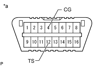
Text in Illustration *a Front view of DLC3 Using SST, connect and disconnect terminals 12 (TS) and 4 (CG) of the DLC3 4 times or more within 8 seconds.
SST 09843-18040 -
Check that the slip indicator light comes on.
-
-
Perform zero point calibration of the yaw rate and acceleration sensor and store the system information.
-
Turn the engine switch off.
-
Check that the steering wheel is centered.
-
Check that the shift lever is in P.
Note
-
DTCs 36 (Zero Point Calibration of Yaw Rate Sensor Undone) and 98 (Zero Point Calibration of Acceleration Sensor Undone) are stored if the shift lever is not in P.
-
If a DTC is output that indicates zero point calibration is incomplete, repeat the procedure starting at the step for clearing the zero point calibration data and system information.
-
-
Text in Illustration *a Front view of DLC3 Using SST, connect terminals 12 (TS) and 4 (CG) of the DLC3.
SST 09843-18040 -
Turn the engine switch on (IG).
-
Keep the vehicle stationary on a level surface for 5 seconds or more.
-
Check that the slip indicator light comes on for several seconds and then blinks in the test mode pattern (0.125 seconds on and 0.125 seconds off).
Tech Tips
-
If the slip indicator light does not blink, perform zero point calibration again.
-
The zero point calibration is performed only once after the system enters test mode.
-
Calibration cannot be performed again until the stored data is cleared.
-
-
Turn the engine switch off and disconnect SST from the DLC3.
-
-
Check if DTC 13 (ECU Initial Setting Incomplete) is output.
Tech Tips
If DTC 13 is not output, calibration was performed successfully.
-
-
-
INITIALIZATION RELATED TO VARIABLE GEAR RATIO STEERING
-
STEERING ANGLE SENSOR INITIALIZATION (to obtain a tire angle (during straight-ahead driving) signal)
-
Turn the engine switch on (IG), and check that the master warning light illuminates for a few seconds.
Note
If the warning light remains on, repair the applicable system.
-
Drive the vehicle on a straight road at 35 km/h (22 mph) or more for 5 seconds or more.
Tech Tips
-
At this point, the steering wheel will still remain off-center by 5 to 10°.
-
In this step, the neutral position of the steering wheel is restored from the steering control ECU memory.
-
-
Confirm that steering angle sensor initialization is completed (using the tester).
-
Enter the VGRS menu using the tester. Select "Straight Angle Valid Flag" from "Data List". Check if the steering angle sensor has obtained a tire angle (during straight-ahead driving) signal.
Standard "Valid" is displayed on the tester screen.
-
-
Confirm that steering angle sensor initialization is completed (not using the tester).
-
Stop the vehicle (engine running).
-
Slowly turn the steering wheel from lock to lock.
-
If it turns approximately 2.7 turns, steering angle sensor initialization is completed. If it turns approximately 3.2 turns, steering angle sensor initialization is not completed.
Note
If the steering wheel turns approximately 3.2 turns, drive the vehicle on a straight road at 35 km/h (22 mph) or more for 5 seconds or more. Then confirm the initialization again.
Note
Use this procedure to center the steering wheel if:
-
The steering actuator assembly has been replaced.
-
The steering control ECU has been replaced.
-
The steering column or steering intermediate shaft has been disconnected.
-
The steering wheel is still off-center after completing the steering angle sensor initialization.
-
-
-
-
-
CALIBRATION RELATED TO VARIABLE GEAR RATIO STEERING
Note
Use this procedure to center the steering wheel if:
-
The steering actuator assembly has been replaced.
-
The steering control ECU has been replaced.
-
The steering column or steering intermediate shaft has been disconnected.
-
The steering wheel is still off-center after completing the steering angle sensor initialization.
-
VGRS SYSTEM CALIBRATION PROCEDURE (WHEN USING SST CHECK WIRE)
-
FACE TIRES STRAIGHT AHEAD (Procedure A)
Note
Drive the vehicle to confirm that the steering wheel is centered.
-
CHECK DTC (Procedure B)
-
Check for DTCs.
Result Result Proceed to DTC C1591/51 is not output Procedure C DTC C1591/51 is output Procedure D
-
-
PERFORM ACTUATOR ANGLE INITIALIZATION (Procedure C)
- SST
- 09843-18040
Note
If the procedures from *1 to *2 are not completed within 1 minute, or if errors are made during these procedures, perform the initialization again from the beginning.
-
Start the engine.
-
Center the steering wheel.
-
Using SST, connect terminals 12 (TS) and 4 (CG), and 13 (TC) and 4 (CG) of the DLC3.*1
-
Disconnect SST from terminal 12 (TS) of the DLC3, and turn the steering wheel to the left 180° or more.
-
Connect SST to terminal 12 (TS) of the DLC3.
-
Disconnect SST from terminal 13 (TC) of the DLC3, and turn the steering wheel to the right 180° or more.
-
Connect SST to terminal 13 (TC) of the DLC3.*2
Tech Tips
If the master warning light comes on, DTC C1591/51 is stored.
-
Disconnect SST from the DLC3.
-
Turn the engine switch off.
-
FACE TIRES STRAIGHT AHEAD (Procedure D)
-
Confirm that the steering wheel is centered when facing the tires straight ahead.
Note
Drive the vehicle to confirm that the steering wheel is centered.
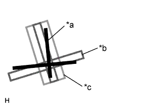
Result Result Proceed to Steering wheel is off-center Procedure E Steering wheel is centered Procedure H
-
-
UNLOCK STEERING ACTUATOR (Procedure E)
Note
Make sure the engine is not running.
-
Turn the engine switch off.
-
Disconnect the cable from the negative (-) battery terminal.
-
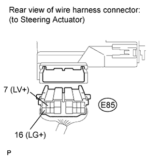
Disconnect the E85 connector from the steering actuator.
-
Connect a jumper wire from terminal 7 (LV+) of the steering actuator to the positive (+) 12 V battery terminal and another jumper wire from terminal 16 (LG+) of the steering actuator to the negative (-) 12 V battery terminal.
Note
Do not apply voltage for more than 3 minutes.
-
-
STEERING CENTER ADJUSTMENT (Procedure F)
-
Center the steering wheel.
Note
If the centering of the spiral cable was not confirmed when the steering wheel was installed, confirm the centering of the spiral cable.
-
-
LOCK STEERING ACTUATOR (Procedure G)
-
Disconnect the positive (+) and negative (-) 12 V battery jumper wires from the steering actuator.
-
Connect the E85 connector to the steering actuator.
-
Connect the cable to the negative (-) battery terminal.
-
Turn the steering wheel approximately 3° to the left and right. Confirm that the reaction force can be felt.
Note
-
If the above procedures are not followed correctly, a DTC will be stored. If a DTC is stored, perform the above procedures again and then check for DTCs.
-
Perform these procedures with the engine switch off.
-
-
-
ADJUST ACTUATOR ANGLE (Procedure H)
- SST
- 09843-18040
Tech Tips
Activating and ending test mode will complete actuator angle adjustment.
-
Make sure the engine switch is off.
Note
Do not touch the steering wheel during these procedures.
-
Using SST, connect terminals 12 (TS) and 4 (CG) of the DLC3.
-
Turn the engine switch on (IG).
-
Confirm that "VGRS Test Mode" is displayed on the multi-information display when test mode is activated.
Tech Tips
Wait approximately 5 seconds.
-
Turn the engine switch off.
-
Disconnect SST from terminals 12 (TS) and 4 (CG) of the DLC3.
-
Turn the engine switch on (IG) again.
-
CHECK MASTER WARNING LIGHT (Procedure I)
-
Confirm that the master warning light is off.
-
Turn the engine switch off, then on (IG).
-
Confirm that the master warning light is operating normally.
-
-
CHECK STEERING WHEEL OPERATION (Procedure J)
-
Start the engine.
-
Perform the steering angle sensor initialization.
-
Turn the steering wheel from lock to lock and check that it rotates approximately 2.7 turns.
-
Drive the vehicle and confirm that the steering wheel is centered.
-
-
-
VGRS SYSTEM CALIBRATION PROCEDURE (WHEN USING INTELLIGENT TESTER)
-
FACE TIRES STRAIGHT AHEAD (Procedure A)
Note
Drive the vehicle to confirm that the steering wheel is centered.
-
PERFORM VGRS SYSTEM CALIBRATION (Procedure B)
-
Connect the intelligent tester to the DLC3.
-
Turn the engine switch on (IG).
-
Turn the tester on.
-
Enter the following menus: Chassis / VGRS / Utility / Steering Angle Adjust.
Then, press "Next".
-
Follow the instructions on the tester, and press "Next".
Note
Press the "Next" key even if DTC C15B4/71 is output.
-
Follow the instructions on the tester, and press "Next".
-
Follow the instructions on the tester, and press "Next".
Note
Ensure that the engine switch is off.
-
Follow the instructions on the tester, and press "Next".
-
Follow the instructions on the tester, and press "Next".
Note
If the centering of the spiral cable was not confirmed when the steering wheel was installed, confirm the centering of the spiral cable.
-
Follow the instructions on the tester, and press "Next".
Note
Do not touch the steering wheel during these procedures.
-
Follow the instructions on the tester, and press "Next".
-
Follow the instructions on the tester, and press "Next".
Note
Do not touch the steering wheel during these procedures.
-
"NOW CALIBRATING" is displayed and the display switches automatically to the next screen.
Note
Do not touch the steering wheel during these procedures.
-
"Steering Angle Adjust is complete." is displayed. Then, check that the VGRS system calibration is completed normally.
-
Select "Exit" to return the display to the "MENU" screen.
-
-
CHECK MASTER WARNING LIGHT (Procedure C)
-
Confirm that the master warning light is off.
-
Turn the engine switch off.
-
Disconnect the intelligent tester from the DLC3.
-
Turn the engine switch on (IG).
-
Confirm that the master warning light is operating normally.
-
-
CHECK STEERING WHEEL OPERATION (Procedure D)
-
Start the engine.
-
Perform the steering angle sensor initialization.
-
Turn the steering wheel from lock to lock and check that it rotates approximately 2.7 turns.
-
Drive the vehicle and confirm that the steering wheel is centered.
-
-
-
-
REGISTRATION VEHICLE CONTRACT SETTING (G-BOOK System)
-
VEHICLE CONTRACT SETTING
Tech Tips
-
When replacing the multi-media module receiver assembly or telematics transceiver, it is not necessary to cancel the G-BOOK contract. (If cancelled a new G-BOOK contract needs to be created after replacement.)
-
If the multi-media module receiver assembly or the telematics transceiver is replaced on vehicles that do not have a contract for the G-BOOK service, perform the vehicle contract setting.
-
If the multi-media module receiver assembly or the telematics transceiver is replaced on vehicles that have a contract for the G-BOOK service, perform the vehicle contract setting and the procedure to resume the G-BOOK service and to start the emergency call service.
-
Check the ID before replacement (when diagnosis can be activated).
Tech Tips
-
If the multi-media module receiver assembly is replaced, check the G-BOOK ID.
-
If the telematics transceiver is replaced, check the DCM ID.
-
Enter diagnostic mode.
-
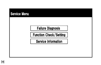
Select "Service Information" on the Service Menu screen.
-
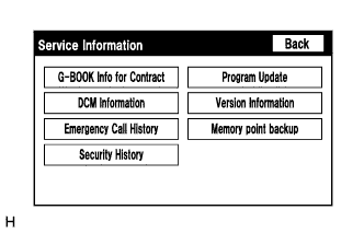
Select "G-BOOK Information for Contract" on the Service Information screen.
-
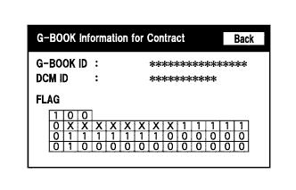
Check the G-BOOK ID or DCM ID.
Tech Tips
The DCM ID is also specified on the telematics transceiver label.
-
-
Replace the multi-media module receiver assembly or the telematics transceiver.
-
Replace the multi-media module receiver assembly or the telematics transceiver at a dealership.
-
-
Check the ID after replacement.
Tech Tips
-
If the multi-media module receiver assembly is replaced, check the G-BOOK ID.
-
If the telematics transceiver is replaced, check the DCM ID.
-
Enter diagnostic mode.
-
Select "Service Information" on the Service Menu screen.
-
Select "G-BOOK Information for Contract" on the Service Information screen.
-
Check the G-BOOK ID or DCM ID.
Tech Tips
The DCM ID is also specified on the telematics transceiver label.
-
-
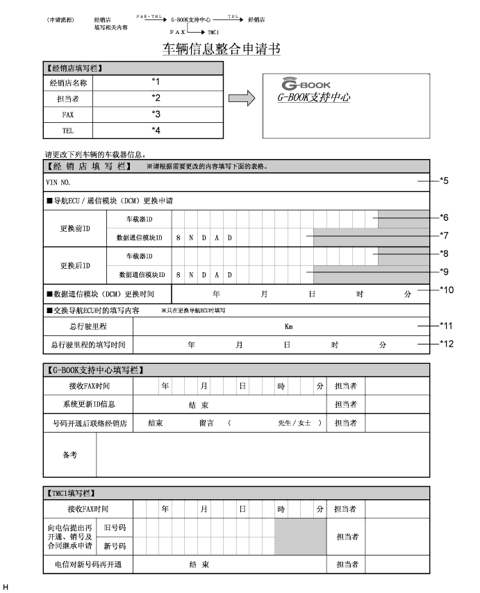
Fill-in the Vehicle Contract Setting Request Form.
-
After filling in the Vehicle Contract Setting Request Form, fax it to the G-BOOK center.
Item Information to Enter Note *1 Enter the dealership name of the applicant. Applicant information *2 Enter the name of the applicant. Applicant information *3 Enter the fax number of the dealership. Applicant information *4 Enter the phone number of the dealership. Applicant information *5 Enter the VIN of the vehicle. Vehicle information *6
-
Enter the G-BOOK ID of the old unit.
-
Left-align the number.
-
If the multi-media module receiver assembly is not being replaced, it is not necessary to enter this item.
Used as change-request information from the dealership *7
-
Enter the DCM ID of the old unit.
-
Left-align the number.
-
If the telematics transceiver is not being replaced, it is not necessary to enter this item.
Used as change-request information from the dealership *8
-
Enter the G-BOOK ID of the new unit installed to the vehicle.
-
Left-align the number.
-
If the multi-media module receiver assembly is not being replaced, it is not necessary to enter this item.
Used as change-request information from the dealership *9
-
Enter the DCM ID of the new unit installed to the vehicle.
-
Left-align the number.
-
If the telematics transceiver is not being replaced, it is not necessary to enter this item.
Used as change-request information from the dealership *10
-
Enter the date when the telematics transceiver is replaced.
-
If the telematics transceiver is not being replaced, it is not necessary to enter this item.
Used as change-request information from the dealership *11 Enter the mileage on the odometer when the multi-media module receiver assembly is replaced. Used as change-request information from the dealership *12 Enter the date that the mileage was recorded. Used as change-request information from the dealership -
-
-
Perform the procedure to resume the G-BOOK service.
Tech Tips
The screen illustrations provided are samples only and may be different from actual screens.
-
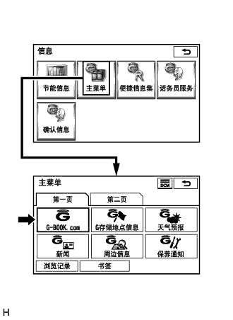
Perform the operations shown in the illustration and select G-BOOK.com.
-
Check that G-BOOK.com is displayed.
-
After the guidance screen is displayed, perform the procedure to resume the G-BOOK service by following the instructions on the screen.
-
-
Perform the procedure to start the emergency call service.
-
After completing the procedure to resume the G-BOOK service, perform the procedure to start the emergency call service by following the instructions on the screen.
Tech Tips
The emergency call service will be available when the procedure is completed successfully.
-
-
-
-
INITIALIZATION RELATED TO PARKING ASSIST MONITOR SYSTEM (w/ Side Monitor System)
-
INITIALIZE PARKING ASSIST MONITOR SYSTEM
-
When "System initializing" is displayed on the multidisplay assembly, correct the steering angle neutral point using the following method.
-
Fully turn the steering wheel to the right and left on flat ground.
Note
Memorizing the steering angle neutral point must be carried out with the engine started. Apply the parking brake, depress the brake pedal, check that the shift lever is in P, and ensure that the vehicle is not moving.
Tech Tips
The "?" button is displayed at the same time as "System initializing". If the "?" button is selected, this method is displayed.
-
-
-
-
CALIBRATION RELATED TO PARKING ASSIST MONITOR SYSTEM (w/ Side Monitor System)
-
ADJUST PARKING ASSIST MONITOR SYSTEM
-
This parking assist monitor system (w/ Side Monitor System) can be set from the diagnostic screen of the multi-display assembly.
-
If the following operations are performed, it is necessary to perform adjustments and checks on the diagnostic screen.
Part Name Operation Adjustment Item Proceed to Steering sensor
-
Removal and installation of the Steering angle sensor
-
Removal and installation of the connector of the steering sensor
Steering angle neutral point (Initialize parking assist monitor system [w/ Side Monitor System]) - Steering angle setting Procedure 2 Replacement Steering angle neutral point (Initialize parking assist monitor system [w/ Side Monitor System]) - Steering angle setting Procedure 2 Multi-media module receiver assembly Replacement Vehicle contract setting - Parking assist ECU Replacement Parking assist ECU initialization Procedure 1 Suspension, tires, etc. The vehicle height changes because of suspension or tire replacement Rear television camera optical axis (Back camera position setting) Procedure 3 Side television camera optical axis (Side camera position setting) - Rear television camera assembly
-
Replacement
-
Installation angle of the rear television camera changes because of the removal and installation of the rear television camera, etc.
Rear television camera optical axis (Back camera position setting) Procedure 3 Tech Tips
-
The adjustment values stored while performing parking assist monitor system (w/ Side Monitor System) calibration are stored in the parking assist ECU.
-
After the engine switch is turned off, the multi-media module receiver assembly records various types of memory and settings. As a result, after turning the engine switch off, make sure to wait for the time specified in the following table before disconnecting the cable from the negative (-) battery terminal.
Waiting Time before Disconnecting Cable from Negative (-) Battery Terminal Specification Waiting Time Vehicle enrolled in G-BOOK system 6 minutes Vehicle not enrolled in G-BOOK system 1 minute
-
-
-
PARKING ASSIST ECU INITIALIZATION (Procedure 1)
Tech Tips
Be sure to check for DTCs before performing this procedure.
-
Preparation for adjustment
-
Park the vehicle with the steering wheel centered.
-
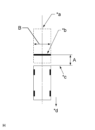
Text in Illustration *a Vehicle Center *b Target Bar for Back Camera Adjustment *c Vehicle End *d Front Side Set a target bar for optical axis adjustment of the rear television camera assembly.
Tech Tips
Only when adjusting the optical axis of the camera assembly, create a target bar for adjustment.
Dimension Area Specification A 825 to 835 mm (2.71 to 2.74 ft.) B 1995 to 2005 mm (6.55 to 6.58 ft.) Tech Tips
-
Set a piece of tape on the ground as the target bar for adjustment. Its width and length are 20 to 30 mm (0.787 to 1.18 in.) and 1995 to 2005 mm (6.55 to 6.58 ft.), respectively. Check the color on the multi-display assembly and choose a tape color which can be easily seen.
-
Before parking the vehicle, be sure to move the vehicle forward and in reverse to check that the tires are facing straight ahead with the steering wheel centered.
-
Check that the back door is fully closed.
-
-
Set a target bar for optical axis adjustment of the side television camera assembly.
Tech Tips
Only when adjusting the optical axis of the camera assembly, create a target bar for adjustment.
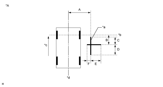
Text in Illustration *A for LHD - - *a Target Bar for Side Camera Adjustment *b Front Wheel Axis *c Front Side *d Vehicle Center 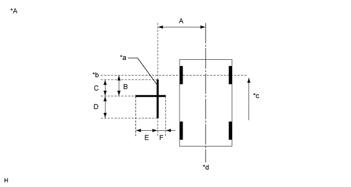
Text in Illustration *A for RHD - - *a Target Bar for Side Camera Adjustment *b Front Wheel Axis *c Front Side *d Vehicle Center Dimension A B C D E F 1183 mm
(3.88 ft.)
1181 mm
(3.87 ft.)
500 mm
(1.64 ft.)
500 mm
(1.64 ft.)
500 mm
(1.64 ft.)
180 mm
(7.09 in.)
Tech Tips
Target bars for side camera adjustment should be made with 2 pieces of 2.5 cm wide tape; one piece should be 100 cm (3.28 ft.) (C+D) and the other should be 68 cm (2.23 ft.) (E+F) long. Check the tape color on the multi-display assembly and choose a tape color which can be easily seen.
-
-
Start diagnostic mode.
Note
Alignment must be performed with the engine running. For this reason, it is necessary to apply the parking brake, depress the brake pedal, and move the shift lever into the P position, and to exercise all other necessary caution to ensure that the vehicle does not begin moving unexpectedly.
Tech Tips
The displayed items may differ depending on vehicle specifications.
-
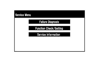
Select "Function Check/Setting" on the [Service Menu] screen.
-
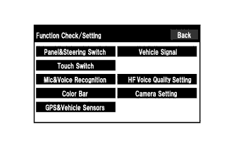
Select "Camera Setting" on the [Function Check/Setting] screen.
-
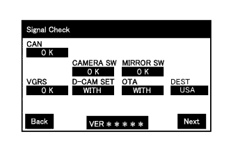
Select "Next" on the [Signal Check] screen.
Note
-
When "CHK" (red) is displayed for any items on the [Signal Check] screen, selecting "Next" will not change the screen to the [Side Camera Position Setting] screen.
-
When "CHK" (red) is displayed for any items on the [Signal Check] screen, perform inspections using the [Signal Check] screen.
Tech Tips
-
When the outer mirrors are retracted, selecting "Next" will not change the screen to the [Side Camera Position Setting] screen.
-
If the screen does not change to the [Side Camera Position Setting] screen even though the outer mirrors are extended, perform the "MIRROR SW" check on the [Signal Check] screen.
-
If the screen does not change to the [Side Camera Position Setting] screen even after "OK" (blue) is displayed as a result of the MIRROR SW check on the [Signal Check] screen, replace the parking assist ECU.
-
-
-
Side Camera Position Setting:
Tech Tips
Colors used on the [Side Camera Position Setting] screen
Text in Illustration *a Target Adjustment Bar for Side Camera Position Setting *b Red Frame *c Yellow Frame
-
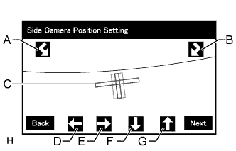
Perform the roll angle adjustment.
-
Select switches A and B to rotate C so that it is parallel to the target adjustment bar.
-
Perform the vertical and horizontal position adjustment.
-
Select the directional switches D, E, F and G to move C so that the target adjustment bar is centered in C.
-
Select "Next" to display [Side Verify Mode].
-
-
Side Verify Mode:
-
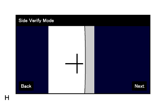
Check that the red cross and the target adjustment bar are aligned.
Tech Tips
If they are not aligned, select "Back" and perform [Side Camera Position Setting] again.
-
Select "Next" to display [Side Camera Signal Check].
-
-
Side Camera Signal Check:
-
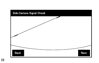
Select "Next" to store the side camera aiming adjustment value and change the screen to the [Steering Angle Setting] screen.
Tech Tips
-
When "Next" is selected, a beep will sound to confirm that the side camera aiming adjustment values have been stored.
-
The adjustment value will not be stored unless "Next" is selected.
-
-
-
Steering Angle Setting:
-
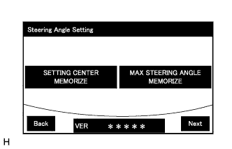
Perform the "STEERING CENTER MEMORIZE" operation.
-
Check that the steering wheel is centered, and then select "STEERING CENTER MEMORIZE".
Tech Tips
When performing removal and installation, or replacement of the television camera, steering angle adjustment is not required.
-
Perform the "MAX STEERING ANGLE MEMORIZE" operation.
-
After adjusting the steering angle neutral point, turn the steering wheel to the left and right lock positions and select "MAX STEERING ANGLE MEMORIZE". The maximum steering angle is then stored and the screen changes to the [Back Camera Position Setting] screen.
Tech Tips
-
The "Next" button does not respond until the system stores the steering angle neutral point and maximum steering angle.
-
It is also possible to start by initially turning the steering to the right side.
-
When "MAX STEERING ANGLE MEMORIZE" is selected, a beep will sound to confirm that the steering adjustment values have been stored.
-
The adjustment value will not be stored unless "MAX STEERING ANGLE MEMORIZE" is selected after turning the steering wheel side to side.
-
When "Back" is selected, the screen changes to [Side Verify Mode] without storing the set values.
-
Even if no DTCs are detected, selecting "MAX STEERING ANGLE MEMORIZE" may not cause the adjustment value to be stored if the steering sensor is malfunctioning.
-
If selecting "MAX STEERING ANGLE MEMORIZE" does not cause the adjustment value to be stored after adjusting the steering angle, replace the steering sensor.
-
-
-
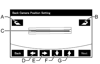
Back Camera Position Setting:
Tech Tips
-
When the back door is open, the "Back door is open. Do not use the rear view monitor when the back door is not completely closed." message will be displayed and camera position setting will not be possible.
-
If the "Back door is open. Do not use the rear view monitor when the back door is not completely closed." message is displayed even when the back door is closed, perform inspections according to Problem Symptoms Table (A back door open warning message is displayed even after back door is closed).
-
Perform the roll angle adjustment.
-
Select switches A and B to rotate C so that it is parallel to the target adjustment bar.
-
Perform the vertical and horizontal position adjustment.
-
Select the directional switches D, E, F and G to move C so that the target adjustment bar is centered in C.
-
Select the "Next" to display [Back Verify Mode].
-
-
Back Verify Mode:
-
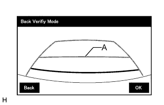
Check that A and the target adjustment bar are overlapping.
-
If the steering angle neutral point is not aligned, perform the "STEERING CENTER MEMORIZE" and "MAX STEERING ANGLE MEMORIZE" operations.
-
If A and the target adjustment bar are not aligned even if the tires are aligned straight ahead, perform the camera position setting operation.
-
Selecting "OK" will return the screen to the [Service Menu] screen, and complete the adjustment.
Tech Tips
-
The update is not completed until "OK" is selected.
-
When "OK" is selected, a beep will sound to confirm that the rear camera aiming adjustment values have been stored.
-
-
-
Finish diagnostic mode.
-
-
STEERING ANGLE SETTING (Procedure 2)
-
Preparation for adjustment
-
Park the vehicle with the steering wheel centered.
-
-
Start diagnostic mode.
Note
Alignment must be performed with the engine running. For this reason, it is necessary to apply the parking brake, depress the brake pedal, and move the shift lever into the P position, and to exercise all other necessary caution to ensure that the vehicle does not begin moving unexpectedly.
Tech Tips
The displayed items may differ depending on vehicle specifications.
-
Select "Function Check/Setting" on the [Service Menu] screen.
-
Select "Camera Setting" on the [Function Check/Setting] screen.
-
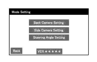
Select "Steering Angle Setting" on the [Mode Setting] screen.
Tech Tips
To select a grayed out item, select and hold the item for 2 seconds or more.
-
Select "Next" on the [Signal Check] screen.
Note
-
When "CHK" (red) is displayed for any items on the [Signal Check] screen, selecting "Next" will not change the screen to the [Steering Angle Setting] screen.
-
When "CHK" (red) is displayed for any items on the [Signal Check] screen, perform inspections using the [Signal Check] screen.
-
-
-
Steering Angle Setting:
-
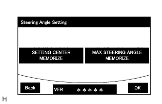
Perform the "STEERING CENTER MEMORIZE" operation.
-
Check that the steering wheel is centered, and then select "STEERING CENTER MEMORIZE".
Tech Tips
When performing removal and installation, or replacement of the television camera, steering angle adjustment is not required.
-
Perform the "MAX STEERING ANGLE MEMORIZE" operation.
After adjusting the steering angle neutral point, turn the steering wheel to the left and right lock positions and select "MAX STEERING ANGLE MEMORIZE". The maximum steering angle is then stored and the screen changes to the [Mode Setting] screen.
Tech Tips
-
The "Next" button does not respond until the system stores the steering angle neutral point and maximum steering angle.
-
It is also possible to start by initially turning the steering to the right side.
-
When "MAX STEERING ANGLE MEMORIZE" is selected, a beep will sound to confirm that the steering adjustment values have been stored.
-
The adjustment value will not be stored unless "MAX STEERING ANGLE MEMORIZE" is selected after turning the steering wheel side to side.
-
When "Back" is selected, the screen changes to [Signal Check] without storing the set values.
-
Even if no DTCs are detected, selecting "MAX STEERING ANGLE MEMORIZE" may not cause the adjustment value to be stored if the steering sensor is malfunctioning.
-
If selecting "MAX STEERING ANGLE MEMORIZE" does not cause the adjustment value to be stored after adjusting the steering angle, replace the steering sensor.
-
-
Select "OK" to display [Mode Setting].
-
-
Finish diagnostic mode.
-
Confirm steering angle adjustment.
Tech Tips
If the steering angle has been adjusted, confirm the steering angle adjustment on the parking assist monitor screen after finishing diagnostic mode.
-
Check on the parking assist screen that the predicted path line moves until the steering wheel is fully turned to either the left or right.
Tech Tips
If the predicted path line stops moving before the steering wheel is fully turned to either the left or right, the steering angle adjustment values have not been stored correctly. In this case, perform "STEERING CENTER MEMORIZE" and "MAX STEERING ANGLE MEMORIZE" again.
-
-
-
BACK CAMERA POSITION SETTING (Procedure 3)
Tech Tips
Be sure to check for DTCs before performing this procedure.
-
Preparation for adjustment
-
Park the vehicle with the steering wheel centered.
-

Text in Illustration *a Vehicle Center *b Target Bar for Back Camera Adjustment *c Vehicle End *d Front Side Set a target bar for optical axis adjustment of the rear television camera.
Tech Tips
Only when adjusting the optical axis of the camera, create a target bar for adjustment.
Dimension Area Specification A 825 to 835 mm (2.71 to 2.74 ft.) B 1995 to 2005 mm (6.55 to 6.58 ft.) Tech Tips
-
Set a piece of tape on the ground as the target bar for adjustment. Its width and length should be 20 to 30 mm (0.787 to 1.18 in.) and 1995 to 2005 mm (6.55 to 6.58 ft.), respectively. Check the color on the multi-display assembly and choose a tape color which can be easily seen.
-
Before parking the vehicle, be sure to move the vehicle forward and in reverse to check that the tires are facing straight ahead with the steering wheel centered.
-
Check that the back door is fully closed.
-
-
-
Start diagnostic mode.
Note
Alignment must be performed with the engine running. For this reason, it is necessary to apply the parking brake, depress the brake pedal, and move the shift lever into the P position, and to exercise all other necessary caution to ensure that the vehicle does not begin moving unexpectedly.
Tech Tips
The displayed items may differ depending on vehicle specifications.
-
Select "Function Check/Setting" on the [Service Menu] screen.
-
Select "Camera Setting" on the [Function Check/Setting] screen.
-
Select "Back Camera Setting" on the [Mode Setting] screen.
Tech Tips
To select a grayed out item, select and hold the item for 2 seconds or more.
-
Select "Next" on the [Signal Check] screen.
Note
-
When "CHK" (red) is displayed for any items on the [Signal Check] screen, selecting "Next" will not change the screen to the [Back Camera Position Setting] screen.
-
When "CHK" (red) is displayed for any items on the [Signal Check] screen, perform inspections using the [Signal Check] screen.
-
-
-
Back Camera Position Setting:
Tech Tips
-
When the back door is open, the "Back door is open. Do not use the rear view monitor when the back door is not completely closed." message will be displayed and camera position setting will not be possible.
-
If the "Back door is open. Do not use the rear view monitor when the back door is not completely closed." message is displayed even when the back door is closed, perform inspections according to Problem Symptoms Table (A back door open warning message is displayed even after back door is closed).
-
Perform the roll angle adjustment.
-
Select switches A and B to rotate C so that it is parallel to the target adjustment bar.
-
Perform the vertical and horizontal position adjustment.
-
Select the directional switches D, E, F and G to move C so that the target adjustment bar is centered in C.
-
Select the "Next" button on the [Back Camera Position Setting] screen.
-
-
Back Verify Mode:
-
Check that A and the target adjustment bar are overlapping.
-
If the steering angle neutral point is not aligned, perform the STEERING CENTER MEMORIZE and MAX STEERING ANGLE MEMORIZE operations.
-
If A and the target adjustment bar are not aligned even if the tires are aligned straight ahead, perform the camera position setting operation.
-
Selecting "OK" will return the screen to the [Service Menu], and complete the adjustment.
Tech Tips
-
The update is not completed until "OK" is selected.
-
When "OK" is selected, a beep will sound to confirm that the rear camera aiming adjustment values have been stored.
-
-
Finish diagnostic mode.
-
-
-
-
INITIALIZATION RELATED TO PARKING ASSIST MONITOR SYSTEM (w/o Side Monitor System)
-
INITIALIZE PARKING ASSIST MONITOR SYSTEM
-
When "System initializing" is displayed on the multimedia module receiver assembly, correct the steering angle neutral point using the following method.
-
Fully turn the steering wheel to the right and left on flat ground.
Note
Memorizing the steering angle neutral point must be carried out with the engine started. Apply the parking brake, depress the brake pedal, check that the shift lever is in P, and ensure that the vehicle is not moving.
Tech Tips
The "?" button is displayed at the same time as "System initializing". If the "?" button is selected, this method is displayed.
-
-
-
-
CALIBRATION RELATED TO PARKING ASSIST MONITOR SYSTEM (w/o Side Monitor System)
-
ADJUST PARKING ASSIST MONITOR SYSTEM (w/o Side Monitor System)
-
This parking assist monitor system (w/o Side Monitor System) can be adjusted using the diagnostic screen of the display.
-
If the following operations are performed, it is necessary to perform adjustments and checks using the diagnostic screen.
Part Name Operation Adjustment Item Proceed to Steering sensor Replacement Steering angle neutral point (Initialize parking assist monitor system [w/o Side Monitor System]) - Steering angle setting Procedure 3
-
Removal and installation of the steering sensor
-
Removal and installation of the connector of the steering sensor
Steering angle neutral point (Initialize parking assist monitor system [w/o Side Monitor System]) - Steering angle setting Procedure 3 Suspension, tires, etc. The vehicle height changes because of suspension or tire replacement Rear television camera assembly optical axis (Back camera position setting) Procedure 2 Rear television camera assembly
-
Replacement
-
Installation angle of the rear television camera assembly changes because of the removal and installation of the rear television camera assembly, etc.
Rear television camera assembly optical axis (Back camera position setting) Procedure 2 Multi-media module receiver assembly Replacement Multi-media module receiver assembly Procedure 1 Note
-
The adjustment values stored while performing parking assist monitor system (w/o Side Monitor System) calibration are stored in the multi-media module receiver assembly.
-
After the engine switch is turned off, the multi-media module receiver assembly records various types of memory and settings. As a result, after turning the engine switch off, make sure to wait for the time specified in the following table before disconnecting the cable from the negative (-) battery terminal.
Waiting Time before Disconnecting Cable from Negative (-) Battery Terminal Condition Waiting Time Vehicle enrolled in G-BOOK system 6 minutes Vehicle not enrolled in G-BOOK system 1 minute
-
-
-
MULTI-MEDIA MODULE RECEIVER ASSEMBLY (PROCEDURE 1)
Tech Tips
Be sure to check for DTCs before performing this procedure.
-
Preparation for adjustment
-
Park the vehicle with the steering wheel centered.
-
Text in Illustration *a Vehicle Center *b Target Bar for Back Camera Adjustment *c Vehicle End *d Front Set a target bar for optical axis adjustment of the rear television camera assembly.
Tech Tips
Only when adjusting the optical axis of the camera, create a target bar for adjustment.
Dimension Area Specification A 824 to 834 mm (2.70 to 2.74 ft.) B 1995 to 2005 mm (6.55 to 6.58 ft.) Tech Tips
-
Set a piece of tape on the ground as the target bar for adjustment. Its width and length should be 20 to 30 mm (0.787 to 1.18 in.) and 1995 to 2005 mm (6.55 to 6.58 ft.), respectively. Check the color on the display and choose a tape color which can be easily seen.
-
Before parking the vehicle, be sure to move the vehicle forward and in reverse to check that the tires are facing straight ahead with the steering wheel centered.
-
Check that the back door is fully closed.
-
-
-
Start diagnostic mode.
Note
The following must be carried out with the engine started. Apply the parking brake, depress the brake pedal, check that the shift lever is in P, and ensure that the vehicle is not moving.
-
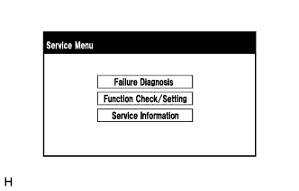
Select "Function Check/Setting" on the [Service Menu] screen.
-
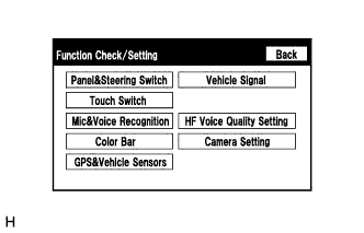
Select "Camera Setting" on the [Function Check/Setting] screen.
-
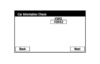
Select "Next" on the [Car Information Check] screen.
-
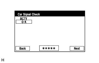
Select "Next" on the [Car Signal Check] screen.
Tech Tips
-
When "CHK" (red) is displayed for any items on the [Car Signal Check] screen, selecting "Next" will not change the screen to the [Steering Angle Setting] screen.
-
When "CHK" (red) is displayed for any items on the [Car Signal Check] screen, perform inspections using the [Car Signal Check] screen.
-
-
-
Steering Angle Setting:
-
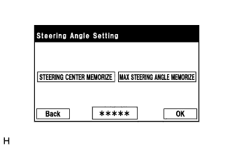
Perform the "STEERING CENTER MEMORIZE" operation.
-
Check that the steering wheel is centered, and then select "STEERING CENTER MEMORIZE".
Tech Tips
When performing removal and installation, or replacement of the rear television camera assembly, steering angle setting is not required.
-
Perform the "MAX STEERING ANGLE MEMORIZE" operation.
-
After performing the steering center memorize operation, turn the steering wheel to the left and right lock positions and select "MAX STEERING ANGLE MEMORIZE". The maximum steering angle is then stored and the screen changes to the [Back Camera Position Setting] screen.
Tech Tips
The "Next" button does not respond until the system memorizes the steering center and maximum steering wheel angle.
Tech Tips
-
It is also possible to start by initially turning the steering to the right side.
-
When "MAX STEERING ANGLE MEMORIZE" is selected, a beep will sound to confirm that the adjustment values have been stored.
-
The adjustment values will not be stored unless "MAX STEERING ANGLE MEMORIZE" is selected after turning the steering wheel from lock to lock.
-
When "BACK" is selected, the screen changes to the [Car Signal Check] screen without storing any values.
-
Even if no DTCs are detected, selecting "MAX STEERING ANGLE MEMORIZE" may not cause the adjustment values to be stored if the steering sensor is malfunctioning.
-
If selecting "MAX STEERING ANGLE MEMORIZE" does not cause the adjustment value to be stored after performing the steering angle setting procedure, replace the steering sensor.
-
-
-
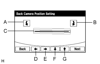
Back Camera Position Setting:
Tech Tips
-
When adjusting the camera optical axis, "Back door is open. Do not use the rear view monitor when the back door is not completely closed." is displayed even after the back door has been closed.
-
When the back door is open, the "Back door is open. Do not use the rear view monitor when the back door is not completely closed." message will be displayed and camera position setting will not be possible.
-
If the "Back door is open. Do not use the rear view monitor when the back door is not completely closed." message is displayed even when the back door is closed, perform inspections according to Problem Symptoms Table (When adjusting the camera optical axis, "Back door is open. Do not use the rear view monitor when the back door is not completely closed." is displayed even after the back door has been closed.).
-
Perform roll angle adjustment.
-
Use switches A and B to rotate C so that it is parallel to the target adjustment bar.
-
Perform vertical and horizontal position adjustment.
-
Use the directional switches D, E, F and G to move C so that the target adjustment bar is centered in C.
-
Select the "Next" button on the [Back Camera Position Setting] screen.
-
-
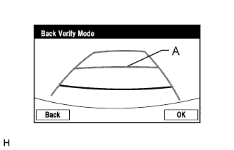
Back Verify Mode:
-
Check that A and the target adjustment bar are overlapping.
-
If the lines are not aligned, perform the "STEERING CENTER MEMORIZE" and "MAX STEERING ANGLE MEMORIZE" operations.
-
If A and the target adjustment bar are not aligned even if the tires are aligned straight ahead, perform the back camera position setting operation.
-
Selecting "OK" will return to the [Service Menu] screen, and complete the adjustment.
Tech Tips
-
The update is not completed until "OK" is selected.
-
When "OK" is selected, a beep will sound to confirm that the adjustment values have been stored.
-
The adjustment values are not stored until the beep has sounded.
-
-
-
Finish diagnostic mode.
-
Confirm steering angle adjustment.
Tech Tips
If the steering angle has been adjusted, confirm the steering angle adjustment on the parking assist monitor screen after finishing diagnosis mode.
-
Check on the parking assist screen that the predicted path line moves until the steering wheel is fully turned to either the left or right.
Tech Tips
If the predicted path line stops moving before the steering wheel is fully turned to either the left or right, the steering angle adjustment values have not been stored correctly. In this case, perform "STEERING CENTER MEMORIZE" and "MAX STEERING ANGLE MEMORIZE" again.
-
-
-
BACK CAMERA POSITION SETTING (PROCEDURE 2)
Tech Tips
Be sure to check for DTCs before performing this procedure.
-
Preparation for adjustment
-
Park the vehicle with the steering wheel centered.
-
Text in Illustration *a Vehicle Center *b Target Bar for Back Camera Position Setting *c Vehicle End *d Front Set a target bar behind the vehicle for optical axis adjustment of the rear television camera assembly (back camera position setting).
Tech Tips
Create a target bar for adjustment only when adjusting the optical axis of the camera.
Dimension Area Specification A 824 to 834 mm (2.70 to 2.74 ft.) B 1995 to 2005 mm (6.55 to 6.58 ft.) Tech Tips
-
Set a piece of tape on the ground as the target bar for adjustment. Its width and length should be 20 to 30 mm (0.787 to 1.18 in.) and 1995 to 2005 mm (6.55 to 6.58 ft.), respectively. Check the color on the multi-display assembly and choose a tape color which can be easily seen.
-
Before parking the vehicle, be sure to move the vehicle forward and in reverse to check that the tires are facing straight ahead with the steering wheel centered.
-
Check that the back door is fully closed.
-
-
-
Start diagnostic mode.
Note
The following must be carried out with the engine started. Apply the parking brake, depress the brake pedal, check that the shift lever is in P, and ensure that the vehicle is not moving.
-
Select "Function Check/Setting" on the [Service Menu] screen.
-
Select "Camera Setting" on the [Function Check/Setting] screen.
-
Select "Next" on the [Car Information Check] screen.
-
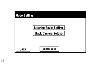
Select "Back Camera Setting" on the [Mode Setting] screen.
Tech Tips
To select a grayed out item, select and hold the item for 2 seconds or more.
-
Select "Next" on the [Car Signal Check] screen.
Tech Tips
-
When "CHK" (red) is displayed for any items on the [Car Signal Check] screen, selecting "Next" will not change the screen to the [Back Camera Position Setting] screen.
-
When "CHK" (red) is displayed for any items on the [Car Signal Check] screen, perform inspections using the [Car Signal Check] screen.
-
-
-
Back Camera Position Setting:
Tech Tips
-
When the back door is open, the "Back door is open. Do not use the rear view monitor when the back door is not completely closed." message will be displayed and camera position setting will not be possible.
-
If the "Back door is open. Do not use the rear view monitor when the back door is not completely closed." message is displayed even when the back door is closed, perform inspections according to Problem Symptoms Table (When adjusting the camera optical axis, "Back door is open. Do not use the rear view monitor when the back door is not completely closed." is displayed even after the back door has been closed.).
-
Perform roll angle adjustment.
-
Use switches A and B to rotate C so that it is parallel to the target adjustment bar.
-
Perform vertical and horizontal position adjustment.
-
Use the directional switches D, E, F and G to move C so that the target adjustment bar is centered in C.
-
Select the "Next" button on the [Back Camera Position Setting] screen.
-
-
Back Verify Mode:
-
Check that A and the target adjustment bar are overlapping.
-
If the lines are not aligned, perform the "STEERING CENTER MEMORIZE" and "MAX STEERING ANGLE MEMORIZE" operations.
-
If A and the target adjustment bar are not aligned even if the tires are aligned straight ahead, perform the back camera position setting operation.
-
Selecting "OK" will return to the [Service Menu], and complete the adjustment.
Tech Tips
-
The update is not completed until "OK" is selected.
-
When "OK" is selected, a beep will sound to confirm that the adjustment values have been stored.
-
The adjustment values are not stored until the beep has sounded.
-
-
Finish diagnostic mode.
-
-
-
Steering Angle Setting (PROCEDURE 3)
Tech Tips
If the vehicle width extension lines and predicted path lines are not aligned when the steering wheel is centered, or if the predicted path line does not move before the steering wheel is fully turned to either the left or right, perform Steering Angle Setting.
-
Center the steering wheel and stop the vehicle.
-
Start diagnostic mode.
Note
The following must be carried out with the engine started. Apply the parking brake, depress the brake pedal, check that the shift lever is in P, and ensure that the vehicle is not moving.
-
Select "Function Check/Setting" on the [Service Menu] screen.
-
Select "Camera Setting" on the [Function Check/Setting] screen.
-
Select "Next" on the [Car Information Check] screen.
-
Select "Steering Angle Setting" on the [Mode Setting] screen.
Tech Tips
To select a grayed out item, select and hold the item for 2 seconds or more.
-
Select "Next" on the [Car Signal Check] screen to display the [Steering Angle Setting] screen.
Tech Tips
-
When "CHK" (red) is displayed for any items on the [Car Signal Check] screen, selecting "Next" will not change the screen to the [Steering Angle Setting] screen.
-
When "CHK" is displayed for any items on the [Car Signal Check] screen, perform inspections using the [Car Signal Check] screen.
-
-
-
Steering Angle Setting:
-
Check that the steering wheel is centered (approximately +/- 5 degrees or less) and select "STEERING CENTER MEMORIZE".
-
After the centered steering position is memorized, turn the steering wheel to the left and then to the right full lock positions and select "MAX STEERING ANGLE MEMORIZE".
Tech Tips
It is also possible to start by initially turning the steering wheel to the right side.
-
Select "MAX STEERING ANGLE MEMORIZE" to store the steering angle adjustment value and change the screen to the [Mode Setting] screen.
Tech Tips
-
When "MAX STEERING ANGLE MEMORIZE" is selected, a beep will sound to confirm that the steering angle adjustment values have been stored.
-
The adjustment values will not be stored unless "MAX STEERING ANGLE MEMORIZE" is selected.
-
When "BACK" is selected, the screen changes to Car Signal Check without storing the set values.
-
If the "Steering Angle Settings" have not been adjusted, selecting "MAX STEERING ANGLE MEMORIZE" will not cause the adjustment values to be stored.
-
Even if no DTCs are detected, selecting "MAX STEERING ANGLE MEMORIZE" may not cause the adjustment value to be stored if the steering sensor is malfunctioning.
-
If selecting "MAX STEERING ANGLE MEMORIZE" does not cause the adjustment value to be stored after adjusting the steering angle, replace the steering sensor.
-
-
-
Finish diagnostic mode.
-
Confirm steering angle adjustment.
Tech Tips
If the steering angle has been adjusted, confirm the steering angle adjustment on the parking assist monitor screen after finishing diagnosis mode.
-
Check on the parking assist screen that the predicted path line moves until the steering wheel is fully turned to either the left or right.
Tech Tips
If the predicted path line stops moving before the steering wheel is fully turned to either the left or right, the steering angle adjustment values have not been stored correctly. In this case, perform "STEERING CENTER MEMORIZE" and "MAX STEERING ANGLE MEMORIZE" again.
-
-
-
-
INITIALIZATION RELATED TO SIDE MONITOR SYSTEM
-
INITIALIZE SIDE MONITOR SYSTEM
-
When "System initializing" is displayed on the multimedia module receiver assembly, correct the steering angle neutral point using the following method.
-
Fully turn the steering wheel to the right and left on flat ground.
Note
Memorizing the steering angle neutral point must be carried out with the engine started. Apply the parking brake, depress the brake pedal, check that the shift lever is in P, and ensure that the vehicle is not moving.
Tech Tips
The "?" button is displayed at the same time as "System initializing". If the "?" button is selected, this method is displayed.
-
-
-
-
CALIBRATION RELATED TO SIDE MONITOR SYSTEM
-
ADJUST SIDE MONITOR SYSTEM
-
This side monitor system can be set from the diagnostic screen of the multi-display assembly.
-
If the following operations are performed, it is necessary to perform adjustments and checks on the diagnostic screen.
Part Name Operation Adjustment Item Proceed to Steering sensor
-
Removal and installation of the Steering angle sensor
-
Removal and installation of the connector of the Steering angle sensor
-
Replacement
Steering angle neutral point - Steering angle setting - Multi-media module receiver assembly Replacement Vehicle contract setting - Parking assist ECU Replacement Parking assist ECU initialization - Suspension, tires, etc. The vehicle height changes because of suspension or tire replacement Rear television camera optical axis (Camera position setting) - Side television camera optical axis (Camera position setting) Procedure 1 Side television camera assembly
-
Replacement
-
Installation angle of the side television camera changes because of the removal and installation of the side television camera, etc.
Side television camera optical axis (Camera position setting) Procedure 1 Outer rear view mirror assembly Replacement Side television camera optical axis (Camera position setting) Procedure 1 Tech Tips
-
The adjustment values stored while performing side monitor system calibration are stored in the parking assist ECU.
-
After the engine switch is turned off, the multi-media module receiver assembly records various types of memory and settings. As a result, after turning the engine switch off, make sure to wait for the time specified in the following table before disconnecting the cable from the negative (-) battery terminal.
Waiting Time before Disconnecting Cable from Negative (-) Battery Terminal Specification Waiting Time Vehicle enrolled in G-BOOK system 6 minutes Vehicle not enrolled in G-BOOK system 1 minute
-
-
-
SIDE CAMERA SETTING (Procedure 1)
Tech Tips
Be sure to check for DTCs before performing this procedure.
-
Preparation for adjustment
-
Park the vehicle with the steering wheel centered.
-
Set a target bar for optical axis adjustment of the rear television camera assembly.
Tech Tips
Only when adjusting the optical axis of the camera assembly, create a target bar for adjustment.
Dimension Area Specification A 825 to 835 mm (2.71 to 2.74 ft.) B 1995 to 2005 mm (6.55 to 6.58 ft.) Text in Illustration *a Vehicle Center *b Target Bar for Back Camera Adjustment *c Vehicle End *d Front Side Tech Tips
-
Set a piece of tape on the ground as the target bar for adjustment. Its width and length are 20 to 30 mm (0.787 to 1.18 in.) and 1995 to 2005 mm (6.55 to 6.58 ft.), respectively. Check the color on the multi-display assembly and choose a tape color which can be easily seen.
-
Before parking the vehicle, be sure to move the vehicle forward and in reverse to check that the tires are facing straight ahead with the steering wheel centered.
-
Check that the back door is fully closed.
-
-
Set a target bar for optical axis adjustment of the side television camera assembly.
Tech Tips
Only when adjusting the optical axis of the camera assembly, create a target bar for adjustment.
Text in Illustration *A for LHD - - *a Target Bar for Side Camera Adjustment *b Front Wheel Axis *c Front Side *d Vehicle Center
Text in Illustration *A for RHD - - *a Target Bar for Side Camera Adjustment *b Front Wheel Axis *c Front Side *d Vehicle Center Dimension A B C D E F 1183 mm
(3.88 ft.)
1181 mm
(3.87 ft.)
500 mm
(1.64 ft.)
500 mm
(1.64 ft.)
500 mm
(1.64 ft.)
180 mm
(7.09 in.)
Tech Tips
Target bars for side camera adjustment should be made with 2 pieces of 2.5 cm wide tape; one piece should be 100 cm (3.28 ft.) (C+D) and the other should be 68 cm (2.23 ft.) (E+F) long. Check the tape color on the multi-display assembly and choose a tape color which can be easily seen.
-
-
Start diagnostic mode.
Note
Alignment must be performed with the engine running. For this reason, it is necessary to apply the parking brake, depress the brake pedal, and move the shift lever into the P position, and to exercise all other necessary caution to ensure that the vehicle does not begin moving unexpectedly.
Tech Tips
The displayed items may differ depending on vehicle specifications.
-
Select "Function Check/Setting" on the [Service Menu] screen.
-
Select "Camera Setting" on the [Function Check/Setting] screen.
-
Select "Side Camera Setting" on the [Mode Setting] screen.
Tech Tips
To select a grayed out item, select and hold the item for 2 seconds or more.
-
Select "Next" on the [Signal Check] screen.
Note
-
When "CHK" (red) is displayed for any items on the [Signal Check] screen, selecting "Next" will not change the screen to the [Side Camera Position Setting] screen.
-
When "CHK" (red) is displayed for any items on the [Signal Check] screen, perform inspections using the [Signal Check] screen.
Tech Tips
-
When the outer mirrors are retracted, selecting "Next" will not change the screen to the [Side Camera Position Setting] screen.
-
If the screen does not change to the [Side Camera Position Setting] screen even though the outer mirrors are extended, perform the "MIRROR SW" check on the [Signal Check] screen.
-
If the screen does not change to the [Side Camera Position Setting] screen even after "OK" (blue) is displayed as a result of the MIRROR SW check on the [Signal Check] screen, replace the parking assist ECU.
-
-
-
Side Camera Position Setting:
Tech Tips
Colors used on the [Side Camera Position Setting] screen
Text in Illustration *a Target Adjustment Bar for Side Camera Position Setting *b Red Frame *c Yellow Frame
-
Perform the roll angle adjustment.
-
Select switches A and B to rotate C so that it is parallel to the target adjustment bar.
-
Perform the vertical and horizontal position adjustment.
-
Select the directional switches D, E, F and G to move C so that the target adjustment bar is centered in C.
-
Select "Next" to display [Side Verify Mode].
-
-
Side Verify Mode:
-
Check that the red cross and the target adjustment bar are aligned.
Tech Tips
If they are not aligned, select "Back" and perform [Side Camera Position Setting] again.
-
Select "Next" to display [Side Camera Signal Check].
-
-
Side Camera Signal Check:
-
Select "OK" to store the side camera aiming adjustment value and change the screen to the [Service Menu] screen.
Tech Tips
-
When "OK" is selected, a beep will sound to confirm that the side camera aiming adjustment values have been stored.
-
The adjustment value will not be stored unless "Back" is selected.
-
-
-
Finish diagnostic mode.
-
-
-
INITIALIZATION RELATED TO AIR CONDITIONING SYSTEM
-
INITIALIZATION SERVO MOTOR
-
Turn the engine switch off.
-
Connect the intelligent tester to the DLC3.
-
Turn the engine switch on (IG).
-
Press the blower OFF switch.
-
Turn the intelligent tester on.
-
Enter the following menus: Body Electrical / Air Conditioner / Utility / Servomotor Initialization.
-
According to the intelligent tester display, perform servomotor initialization.
Tech Tips
During initialization, the AUTO indicator light comes on, and then goes off when initialization has finished.
-
According to the intelligent tester display, select the "Exit" switch to finish initialization.
-
-
-
INITIALIZATION RELATED TO POWER WINDOW
-
INITIALIZE POWER WINDOW CONTROL SYSTEM (POWER WINDOW REGULATOR MOTOR (ALL DOORS))
CAUTION:
When the power window regulator motor is reinstalled or replaced, the power window control system must be initialized. Functions such as the auto up/down, jam protection and key-off do not operate if the initialization is not performed.
Tech Tips
When the battery is replaced, it is not necessary to initialize the power window regulator motor.
Note
-
When the power window regulator motor is replaced, DTC B2313 is output. Clear the DTC after the initialization.
-
When performing initialization, do not perform any other procedures.
-
After a door glass or a door glass run has been replaced, the jam protection function may operate unexpectedly when the auto up function is used, due to detection of a value different from the operation learned value of the door glass movement speed. In such cases, the auto up function can be resumed by repeating the following operation at least 5 times:
-
Open the power window by fully pushing down the power window switch.
-
Close the power window by fully pulling up the power window switch and holding it at the auto up position.
-
If the initialization is not completed properly, the LIN communication system may have a malfunction.
-
Initialization procedures when replacing the power window regulator motor with a new one:
-
Connect the battery and turn the engine switch on (IG) (at this time, the LED on the power window switch blinks to indicate that it is ready for initialization).
-
Fully open the window by fully pushing the power window switch, and hold the switch for 1 second or more after the window is fully opened.
-
Fully close the power window by fully pulling the power window switch, and hold the switch for 1 second or more after the window is fully closed to reset the glass position. The LED on the power window switch stops blinking and illuminated to indicate that the initialization is complete.
-
-
Initialization procedures when removing/installing the power window regulator motor:
-
Connect the battery and turn the engine switch on (IG).
-
Fully close the power window by fully pulling the power window switch, and hold the switch for 6 seconds or more after the window is fully closed (if the power window does not move or stops halfway even when the switch is fully pulled, release the switch and fully pull it again).
-
Fully open the window by pushing down the power window switch, and hold the switch for 1 second or more after the window is fully opened.
-
Release the power window switch. Then fully push and hold the switch for 4 seconds or more.
-
Fully close the power window by fully pulling the power window switch, and hold the switch for 1 second or more after the window is fully closed to reset the glass position and complete the initialization.
-
-
Initialization procedures when the power window does not fully open:
-
Connect the battery and turn the engine switch on (IG).
-
Fully close the power window by fully pulling the power window switch, and hold the switch for 6 seconds or more after the window is fully closed (if the power window does not move or stops halfway even when the switch is fully pulled, release the switch and fully pull it again).
-
Fully open the window by pushing down the power window switch, and hold the switch for 1 second or more after the window is fully opened.
-
Release the power window switch. Then fully push and hold the switch 4 seconds or more.
-
Fully close the power window by fully pulling the power window switch, and hold the switch 1 second or more after the window is fully closed to reset the glass position and complete the initialization.
-
-
-
-
INITIALIZATION RELATED TO SLIDING ROOF
-
INITIALIZE SLIDING ROOF DRIVE GEAR
Note
-
When the sliding roof glass is replaced or removed and installed, or the drive gear assembly is replaced, the sliding roof drive gear requires initialization (pulse sensor initial position setting), as the glass position cannot be determined. If initialization is not performed, the auto slide open and close/tilt up and down function may not operate, or the sliding roof may move in reverse or become misaligned.
-
During initialization, do not apply a physical shock, such as opening/closing a door or driving the vehicle at 5 km/h (3.10 mph) or more, to the vehicle and do not perform the following electrical operations:
-
Cranking the engine
-
Turning the engine switch from on (IG) to off
-
Operating the power window switches
-
Operating the window defogger switch
-
Operating the blower switch
-
Locking/Unlocking the door
-
Operating the headlight dimmer switch
Tech Tips
When the cable is disconnected and reconnected to the negative (-) battery terminal or the drive gear connector is disconnected and reconnected, the sliding roof drive gear (pulse sensor initial position setting) initialization is not necessary.
-
Perform initialization according to the table below.
Condition of Sliding Roof Proceed to Auto slide open and close/tilt up and down function does not operate Procedure A Sliding roof moves in reverse direction during tilt down operation Procedure B Sliding roof moves in reverse direction during slide close operation Procedure C
-
Procedure A
-
Turn the engine switch on (IG).
-
Open the sliding roof to the fully tilt up position.
-
Press and hold the UP switch to perform the following operations: tilt up → approximately 10 second pause → tilt down → slide open → slide close.
Note
Make sure not to release the switch during the initialization. If the switch is released, perform the initialization again.
-
Continue to hold the switch for 1 second or more after the sliding roof stops in the fully closed position, and then release it.
-
The initialization is completed.
-
Procedure B
-
Turn the engine switch on (IG).
-
Press the UP switch until the sliding roof stops.
Tech Tips
If the glass becomes misaligned or does not fully tilt up, perform the following operations:
-
Operate the CLOSE switch until the sliding roof stops moving.
-
Operate the UP switch until the sliding roof stops moving, then proceed to the next step.
-
Release the switch.
-
Press and hold the UP switch to perform the following operations: tilt up → approximately 10 second pause → tilt down → slide open → slide close.
Note
Make sure not to release the switch during the initialization. If the switch is released, perform the initialization again.
-
Continue to hold the switch for 1 second or more after the sliding roof stops in the fully closed position, and then release it.
-
The initialization is completed.
-
-
-
-
Procedure C
-
Turn the engine switch on (IG).
-
Press and hold the CLOSE switch to perform the following operations: slide close → move in reverse direction → 10 second pause → slide close → tilt up → tilt down → slide open → slide close.
Note
Make sure not to release the switch during the initialization. If the switch is released, perform the initialization again.
-
Continue to hold the switch for 1 second or more after the sliding roof stops in the fully closed position, and then release it.
-
Check if the auto function is operative.
-
-
-
INITIALIZATION RELATED TO POWER BACK DOOR
-
RESET BACK DOOR CLOSE POSITION
Note
Perform initialization of the power back door system (power back door ECU initialization) if one of the following is performed: 1) The cable is disconnected from the negative (-) battery terminal; 2) a wire harness, the power back door unit or back door lock is replaced or removed/installed; or 3) the ECU-B2 fuse is replaced or removed/installed. If initialization is not performed, the power back door system will not operate.
-
When the back door is open and the cable is disconnected and reconnected to the negative (-) battery terminal, fully close the back door by hand.
Tech Tips
Initialization is not necessary if the cable is disconnected and reconnected to the negative (-) battery terminal while the back door is closed. However, because the power back door ECU recognizes that the back door is locked, the power back door system will not operate if the back door is not unlocked.
-
-
CHECK POWER BACK DOOR FUNCTION
Tech Tips
-
Proceed to Operation Check.
-
If the power back door system does not operate and/or the back door does not open, disconnect the cable from the negative (-) battery terminal. Then wait 10 seconds, reconnect the cable and perform initialization of the power back door system again.
-
-