TIRE PRESSURE WARNING RECEIVER INSTALLATION

-
INSTALL TIRE PRESSURE WARNING ECU AND RECEIVER
-
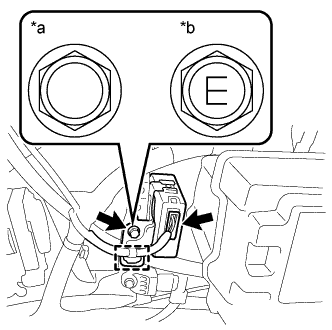
Text in Illustration *a Bolt A *b Bolt B Install the tire pressure warning ECU and receiver with the bolt.
- Torque:
- Bolt A
- 13 N*m { 127 kgf*cm, 9 ft.*lbf }
- Bolt B
- 8.3 N*m { 85 kgf*cm, 73 in.*lbf }
Note
The different marks on the heads of the bolts are shown in the illustration. Check whether the bolt being used is bolt A or bolt B, and then tighten the bolt using the appropriate torque.
-
Connect the connector.
-
Attach the clamp.
-
-
INSTALL FRONT QUARTER TRIM PANEL ASSEMBLY RH
-
CONNECT CABLE TO NEGATIVE BATTERY TERMINAL
Note
When disconnecting the cable, some systems need to be initialized after the cable is reconnected Click here.
-
REGISTRATION OF TRANSMITTER ID
-
INSPECT TIRE PRESSURE WARNING SYSTEM
-
PERFORM INITIALIZATION