FRONT ACCELERATION SENSOR INSTALLATION

-
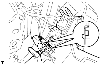
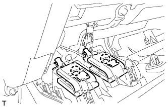
INSTALL ACCELERATION SENSOR (for Driver Side)
-
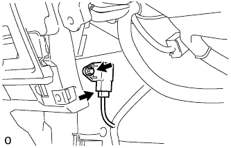
Install the sensor with the bolt.
- Torque:
- 8.0 N*m { 82 kgf*cm, 71 in.*lbf }
-
Connect the connector.
-
-
INSTALL ACCELERATION SENSOR (for Front Passenger Side)
-
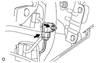
Install the sensor with the bolt.
- Torque:
- 8.0 N*m { 82 kgf*cm, 71 in.*lbf }
-
Connect the connector.
-
-
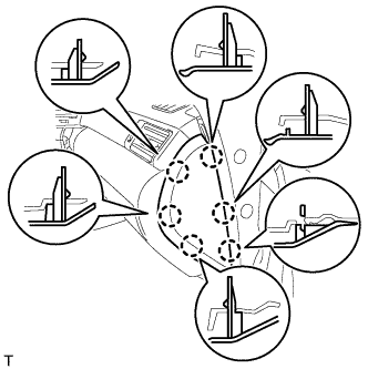
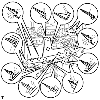
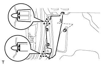
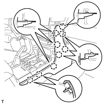
INSTALL STEERING CONTROL ECU WITH JUNCTION BLOCK (for LHD)
-
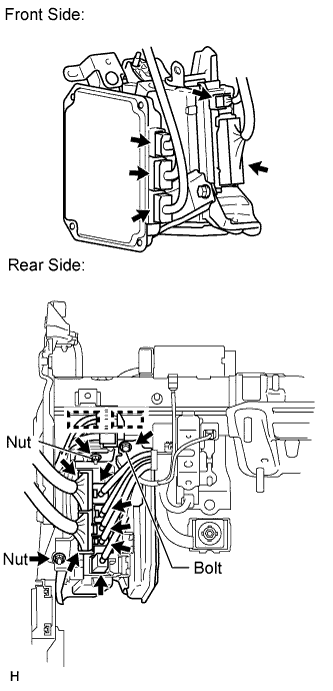
Front Side:
-
Connect the 5 connectors.
-
-
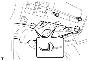
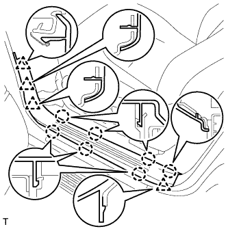
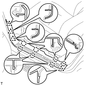
Rear Side:
-
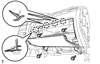
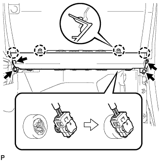
Install the steering control ECU with junction block to the vehicle with the 2 bolts and nut.
- Torque:
- 8.0 N*m { 82 kgf*cm, 71 in.*lbf }
-
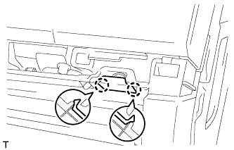
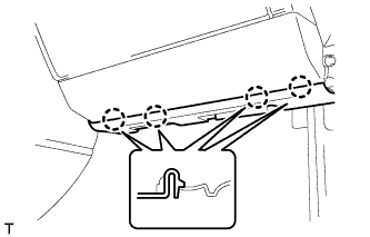
Attach the 2 clamps.
-
Connect the 7 connectors.
-
-
-
INSTALL STEERING CONTROL ECU WITH JUNCTION BLOCK (for RHD)
-
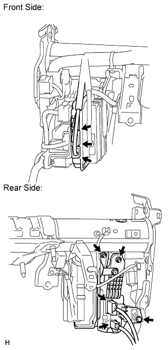
Front Side:
-
Connect the 3 connectors.
-
-
Rear Side:
-
Install the steering control ECU with junction block to the vehicle with the bolt and 2 nuts.
- Torque:
- 8.0 N*m { 82 kgf*cm, 71 in.*lbf }
-
Connect the 2 connectors.
-
-
-
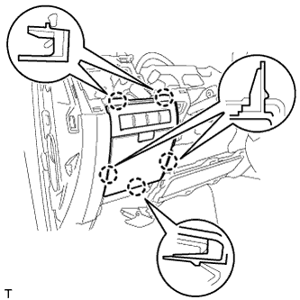
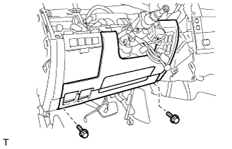
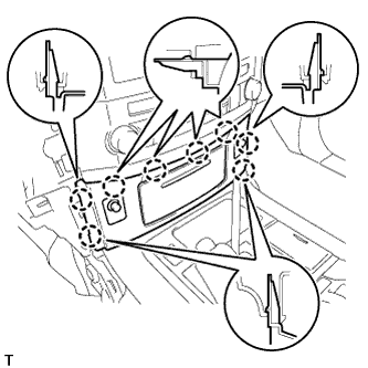
INSTALL LOWER NO. 2 INSTRUMENT PANEL FINISH PANEL
-
Connect the connector.
-
Attach the 4 claws to install the finish panel.
-
Install the 4 bolts.
-
-
INSTALL INSTRUMENT PANEL BOX DOOR KNOB
-
Attach the 2 claws to install the knob.
-
-
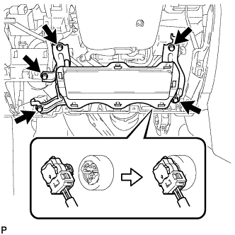
INSTALL FRONT PASSENGER SIDE KNEE AIRBAG ASSEMBLY
-
Connect the connector.
Note
When handling the airbag connector, take care not to damage the airbag wire harness.
-
Attach the 4 claws to install the front passenger side knee airbag.
-
Install the 4 bolts.
- Torque:
- 10 N*m { 102 kgf*cm, 7 ft.*lbf }
-
-
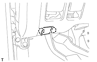
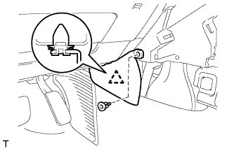
INSTALL COWL SIDE TRIM BOARD RH
-
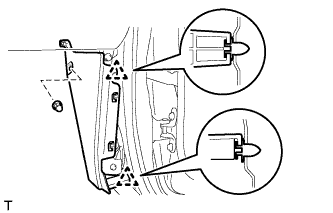
Attach the 2 clips to install the trim board.
-
Install the cap nut.
-
-
INSTALL NO. 2 INSTRUMENT PANEL UNDER COVER SUB-ASSEMBLY
-
Connect the connector.
-
Attach the 4 claws to install the under cover.
-
-
INSTALL FRONT DOOR SCUFF PLATE RH
Tech Tips
Use the same procedures described for the LH side.
-
INSTALL NO. 3 INSTRUMENT CLUSTER FINISH PANEL GARNISH
-
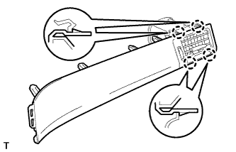
Attach the 4 claws to install the panel garnish.
-
Attach the 11 claws to install the register assembly.
-
-
INSTALL NO. 4 INSTRUMENT PANEL REGISTER ASSEMBLY
-
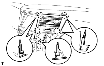
Attach the 5 claws to install the register.
-
-
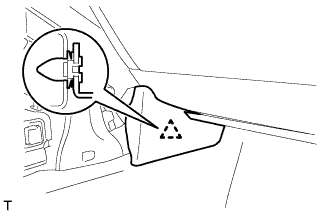
INSTALL INSTRUMENT SIDE PANEL RH
-
w/o Airbag Cut Off Switch:
-
Attach the 6 claws to install the side panel.
-
-
w/ Airbag Cut Off Switch:
-
Connect the connector.
-
Attach the 6 claws to install the side panel.
-
-
-
INSTALL DRIVER SIDE KNEE AIRBAG ASSEMBLY
-
Connect the connector.
Note
When handling the airbag connector, take care not to damage the airbag wire harness.
-
Install the driver side knee airbag with the 5 bolts.
- Torque:
- 10 N*m { 102 kgf*cm, 7 ft.*lbf }
-
-
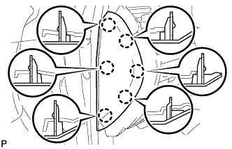
INSTALL INSTRUMENT PANEL BOX ASSEMBLY
-
Connect the connectors.
-
Attach the 5 claws to install the box.
-
-
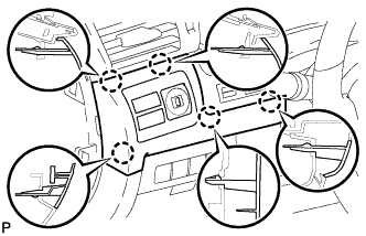
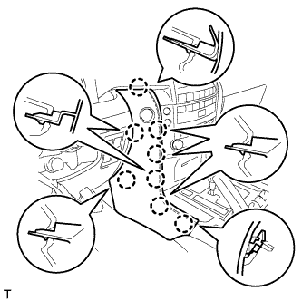
INSTALL LOWER NO. 1 INSTRUMENT PANEL FINISH PANEL
-
Connect the connectors.
-
Attach the 2 claws to install the sensor.
-
Attach the 2 claws to connect the 2 control cables.
-
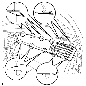
Attach the 16 claws to install the finish panel.
-
Install the 2 bolts.
-
Attach the 2 claws to close the hole cover.
-
-
INSTALL COWL SIDE TRIM BOARD LH
-
Attach the 2 clips to install the trim board.
-
Install the cap nut.
-
-
INSTALL NO. 1 INSTRUMENT PANEL UNDER COVER SUB-ASSEMBLY
-
Connect the connectors.
-
Attach the 3 claws to install the under cover.
-
Install the 2 screws.
-
-
INSTALL FRONT DOOR SCUFF PLATE LH
-
w/o Illumination:
-
Attach the 7 claws and 4 clips to install the scuff plate.
-
-
w/ Illumination:
-
Connect the connector.
-
Attach the 7 claws and 4 clips to install the scuff plate.
-
-
-
INSTALL NO. 1 SWITCH HOLE BASE
-
Connect the connectors.
-
Attach the 5 claws to install the switch hole base.
-
-
INSTALL INSTRUMENT SIDE PANEL LH
-
Attach the 6 claws to install the side panel.
-
-
INSTALL LOWER CENTER INSTRUMENT CLUSTER FINISH PANEL SUB-ASSEMBLY
-
Connect the connectors.
-
Attach the 8 claws to install the panel.
-
-
INSTALL INNER NO. 1 INSTRUMENT PANEL BRACKET COVER RH
-
Attach the clip to install the cover.
-
-
INSTALL LOWER INSTRUMENT PANEL PAD SUB-ASSEMBLY RH
-
Attach the 9 claws to install the panel pad.
-
-
INSTALL INNER NO. 1 INSTRUMENT PANEL BRACKET COVER LH
-
Attach the clip to install the cover.
-
Install the clip.
-
-
INSTALL LOWER INSTRUMENT PANEL PAD SUB-ASSEMBLY LH
-
Connect the connector.
-
Attach the 8 claws to install the panel pad.
-
-
CONNECT CABLE TO NEGATIVE BATTERY TERMINAL
Note
When disconnecting the cable, some systems need to be initialized after the cable is reconnected Click here.
-
CHECK SRS WARNING LIGHT
-
Check the SRS warning light Click here.
-