FRONT UPPER SUSPENSION ARM INSTALLATION

Tech Tips
-
Use the same procedures for the RH side and LH side.
-
The procedures listed below are for the LH side.
-
A bolt without a torque specification is shown in the standard bolt chart Click here.
-
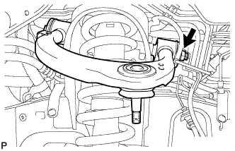
TEMPORARILY INSTALL FRONT SUSPENSION UPPER ARM ASSEMBLY LH
-
Temporarily install the suspension upper arm with the 2 washers, bolt and nut.
Tech Tips
After stabilizing the suspension, tighten the nut.
-
-
CONNECT STEERING KNUCKLE LH
-
Connect the steering knuckle to the suspension upper arm.
-
Install the nut and a new cotter pin.
- Torque:
- 110 N*m { 1122 kgf*cm, 81 ft.*lbf }
Note
If the holes for the cotter pin are not aligned, tighten the nut further up to 60°.
-
-
CONNECT SKID CONTROL SENSOR WIRE

-
Connect the sensor wire to the steering knuckle and upper arm with the bolt and nut.
- Torque:
- 13 N*m { 133 kgf*cm, 9.6 ft.*lbf }
-
-
STABILIZE SUSPENSION
-
Install the front wheels.
- Torque:
- 131 N*m { 1336 kgf*cm, 97 ft.*lbf }
-
Lower the vehicle.
-
Press down on the vehicle several times to stabilize the suspension.
-
-
TIGHTEN FRONT SUSPENSION UPPER ARM ASSEMBLY LH
-
Tighten the nut.
- Torque:
- 185 N*m { 1886 kgf*cm, 136 ft.*lbf }
Note
Perform this procedure with all 4 wheels on the ground.
-
-
INSTALL FRONT HEIGHT CONTROL SENSOR SUB-ASSEMBLY LH
-
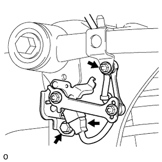
Install the sensor with the bolt and nut.
- Torque:
- for bolt
- 13 N*m { 127 kgf*cm, 9 ft.*lbf }
- for nut
- 5.6 N*m { 57 kgf*cm, 50 in.*lbf }
-
Connect the connector.
-
-
INSTALL FRONT FENDER APRON TRIM PACKING D
-
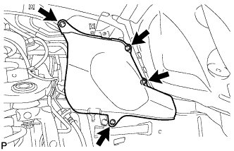
Install the apron trim packing with the 4 clips.
-
-
INSTALL FRONT FENDER APRON TRIM PACKING B
-

Install the apron trim packing with the 4 clips.
-
-
CONNECT CABLE TO NEGATIVE BATTERY TERMINAL
Note
When disconnecting the cable, some systems need to be initialized after the cable is reconnected Click here.
-
PERFORM VEHICLE HEIGHT OFFSET CALIBRATION
-
Perform the vehicle height offset calibration Click here.
-
-
ADJUST FRONT HEIGHT CONTROL SENSOR SUB-ASSEMBLY LH
Note
-
Make adjustments from the link that deviates the most from the specified vehicle height value.
-
When the front and rear are at the same level, make adjustments from the front first.
-
If adjustment cannot be completed through the vehicle height offset calibration, adjust the sensor link using the following procedure.
-
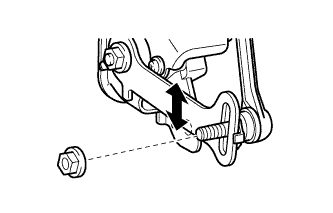
Loosen the nut and adjust the link installation position by moving the height control sensor link up or down in the long hole of the bracket.
Tech Tips
When the link is moved 1 mm (0.0394 in.), the vehicle height changes by approximately 2 mm (0.0787 in.).
-
Tighten the nut of the height control sensor link.
- Torque:
- 5.6 N*m { 57 kgf*cm, 50 in.*lbf }
-
-
PERFORM ZERO POINT CALIBRATION OF G SENSOR
-
Perform the zero point calibration of G sensor Click here.
-
-
ADJUST HEADLIGHT ASSEMBLY
-
Adjust the headlight assembly Click here.
-