FRONT AXLE HUB BOLT REPLACEMENT

Tech Tips
-
Use the same procedures for the LH side and RH side.
-
The procedures listed below are for the LH side.
-
REMOVE FRONT WHEEL
-
DISCONNECT FRONT DISC BRAKE CALIPER ASSEMBLY LH
-
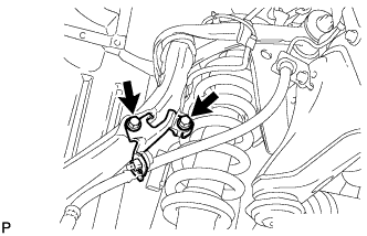
Remove the bolt and nut, and disconnect the brake tube bracket from the steering knuckle.
-
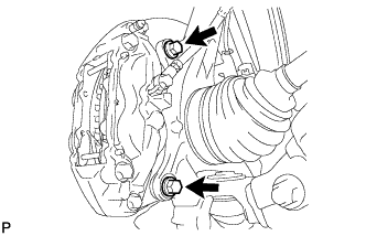
Remove the 2 bolts and disconnect the disc brake caliper from the steering knuckle.
Note
-
Do not disconnect the flexible hose from the disc brake caliper.
-
Do not twist or bend the flexible hose.
-
-
-
REMOVE FRONT DISC
-
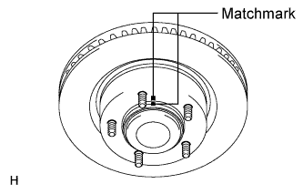
Put matchmarks on the front disc and the axle hub if planning to reuse the disc.
-
Remove the front disc.
-
-
REMOVE FRONT AXLE HUB BOLT LH
-
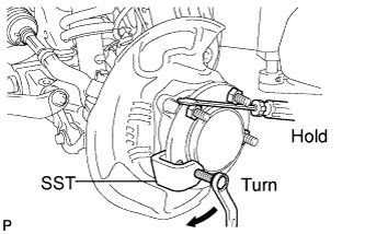
Using SST and a screwdriver or equivalent to hold the axle hub, remove the front axle hub bolt.
- SST
- 09650-17011
Note
Do not damage the threads of the hub bolt.
-
-
INSTALL FRONT AXLE HUB BOLT LH
-
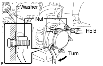
Temporarily install a washer and hub nut to a new hub bolt as shown in the illustration.
Note
Install a hub nut to prevent damage to the hub bolt.
-
Using a screwdriver or equivalent to hold the hub, turn the hub nut until the bottom surface of the hub bolt head touches the axle hub.
-
Remove the washer and hub nut.
Note
Do not damage the threads of the hub bolt.
-
-
INSPECT FRONT AXLE HUB BEARING LOOSENESS
-
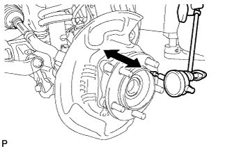
Using a dial indicator, measure the looseness near the center of the axle hub.
Maximum looseness 0.05 mm (0.00197 in.) Note
Ensure that the dial indicator is set at a right angle to the measurement surface.
If the looseness exceeds the maximum, replace the axle hub.
-
-
INSPECT FRONT AXLE HUB RUNOUT
-
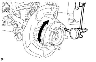
Using a dial indicator, measure the runout on the surface of the axle hub outside the hub bolt.
Maximum runout 0.08 mm (0.00315 in.) Note
Ensure that the dial indicator is set at a right angle to the measurement surface.
If the runout exceeds the maximum, replace the axle hub.
-
-
INSTALL FRONT DISC
-
Align the matchmarks, and then install the front disc.
Tech Tips
When replacing the front disc with a new one, select the installation position where the front disc has the minimum runout.
-
-
CONNECT FRONT DISC BRAKE CALIPER ASSEMBLY LH
-
Connect the front disc brake caliper and install 2 new bolts.
- Torque:
- 99 N*m { 1010 kgf*cm, 73 ft.*lbf }
Note
-
Do not twist the flexible hose.
-
Make sure that the bolts are free from damage and foreign matter.
-
Do not overtighten the bolts.
-
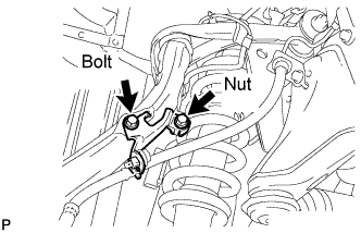
Connect the brake tube bracket to the steering knuckle with the bolt and nut.
- Torque:
- for bolt
- 31 N*m { 316 kgf*cm, 23 ft.*lbf }
- for nut
- 13 N*m { 132 kgf*cm, 10 ft.*lbf }
-
-
INSTALL FRONT WHEEL
- Torque:
- 131 N*m { 1336 kgf*cm, 97 ft.*lbf }