FRONT PROPELLER SHAFT ASSEMBLY INSTALLATION

-
INSTALL FRONT PROPELLER SHAFT ASSEMBLY
-
for Differential Side:
-
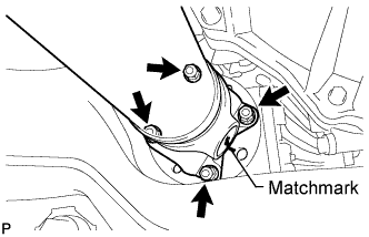
Align the matchmarks on the yoke and differential flange.
-
Connect the propeller shaft with the 4 washers and 4 nuts.
- Torque:
- 88 N*m { 900 kgf*cm, 65 ft.*lbf }
-
-
for Transfer Side:
-
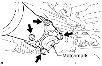
Align the matchmarks on the yoke and transfer flange.
-
Install the propeller shaft with the 4 washers and 4 nuts.
- Torque:
- 88 N*m { 900 kgf*cm, 65 ft.*lbf }
-
-
-
INSTALL PROPELLER SHAFT HEAT INSULATOR
-
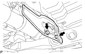
Install the insulator with the 2 bolts.
- Torque:
- 16 N*m { 163 kgf*cm, 12 ft.*lbf }
-
-
INSTALL NO. 2 ENGINE UNDER COVER
-
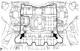
Install the No. 2 engine under cover with the 2 bolts.
- Torque:
- 29 N*m { 296 kgf*cm, 21 ft.*lbf }
-
-
INSTALL NO. 1 ENGINE UNDER COVER SUB-ASSEMBLY
-
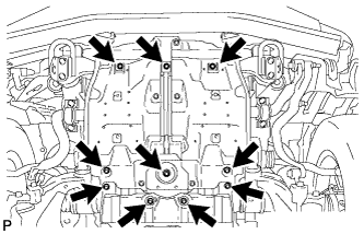
Install the No. 1 engine under cover with the 10 bolts.
- Torque:
- 29 N*m { 296 kgf*cm, 21 ft.*lbf }
-
-
INSTALL FRONT FENDER SPLASH SHIELD SUB-ASSEMBLY LH
-
Push in the clip to install the front fender splash shield sub-assembly LH.
-
Install the 3 bolts and 2 screws.
-
-
INSTALL FRONT FENDER SPLASH SHIELD SUB-ASSEMBLY RH
Tech Tips
Use the same procedure described for the LH side.