FRONT DRIVE SHAFT ASSEMBLY INSTALLATION

-
INSTALL FRONT DRIVE SHAFT ASSEMBLY LH
-
Coat the lip of the differential oil seal with MP grease.
Tech Tips
Inspect the oil seal for wear or damage.
-
Coat the spline of the inboard joint shaft assembly with hypoid gear oil.
-
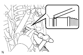
Align the shaft splines and install the drive shaft with a brass bar and hammer.
Note
-
Set the snap ring with the opening side facing downward.
-
Be careful not to damage the oil seal, boot and dust cover.
-
If the outboard joint shaft is new, remove the anti-rust oil on the screw end with non-residue solvent.
Tech Tips
Whether the inboard joint shaft is in contact with the pinion shaft or not can be confirmed from the sound or feeling when driving it.
-
-
-
INSTALL FRONT AXLE ASSEMBLY LH
-
ADD DIFFERENTIAL OIL
-
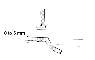
Add differential oil so that the oil level is between 0 to 5 mm (0 to 0.196 in.) from the bottom lip of the differential filler plug hole.
Note
-
Too much or too little oil will lead to differential problems.
-
After changing the oil, drive the vehicle and then check the oil level again.
Differential oil type and viscosity Toyota Genuine Differential gear oil LT 75W-85 GL-5 or equivalent Differential Oil Capacity Item Specified Condition Front Differential 1.85 to 1.95 liters (1.96 to 2.06 US qts., 1.63 to 1.71 Imp. qts.) Rear Differential 4.15 to 4.25 liters (4.39 to 4.49 US qts., 3.66 to 3.74 Imp. qts.) -
-
Front Differential:
-
Using a 10 mm hexagon wrench, install a new gasket and the filler plug.
- Torque:
- 39 N*m { 400 kgf*cm, 29 ft.*lbf }
-
Install the engine under cover Click here.
-
-
Rear Differential:
-
Install a new gasket and the filler plug.
- Torque:
- 49 N*m { 500 kgf*cm, 36 ft.*lbf }
-
-
-
CHECK SPEED SENSOR SIGNAL
-
INSPECT AND ADJUST FRONT WHEEL ALIGNMENT
-
ADJUST HEADLIGHT ASSEMBLY
-
INSTALL NO. 2 ENGINE UNDER COVER
-
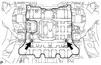
Install the No. 2 engine under cover with the 2 bolts.
- Torque:
- 29 N*m { 296 kgf*cm, 21 ft.*lbf }
-
-
INSTALL NO. 1 ENGINE UNDER COVER SUB-ASSEMBLY
-
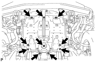
Install the No. 1 engine under cover with the 10 bolts.
- Torque:
- 29 N*m { 296 kgf*cm, 21 ft.*lbf }
-
-
INSTALL FRONT FENDER SPLASH SHIELD SUB-ASSEMBLY LH
-
Push in the clip to install the front fender splash shield sub-assembly LH.
-
Install the 3 bolts and 2 screws.
-
-
INSTALL FRONT FENDER SPLASH SHIELD SUB-ASSEMBLY RH
Tech Tips
Use the same procedure described for the LH side.