FRONT DRIVE SHAFT ASSEMBLY DISASSEMBLY

Tech Tips
-
Use the same procedure for the RH and LH sides.
-
The procedure listed below is for the LH side.
Note
-
When using a vise, place aluminum plates between the part and vise.
-
When using a vise, do not overtighten it.
-
Do not allow brake fluid, front differential oil, gasoline, or battery fluid to contact the front axle inboard joint boot and front axle outboard joint boot, as the front axle inboard joint boot and front axle outboard joint boot may be damaged.
-
REMOVE FRONT AXLE INBOARD JOINT SET SETTING SHAFT SNAP RING
-
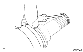
Using a screwdriver, remove the front axle inboard joint set setting shaft snap ring from the front axle inboard joint shaft set LH.
Note
Do not damage the spline of the front axle inboard joint set LH.
-
-
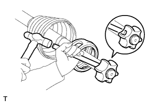
DISCONNECT FRONT NO. 2 AXLE INBOARD JOINT BOOT SETTING CLAMP
-
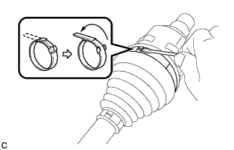
Using a screwdriver, release the staked part of the front No. 2 axle inboard joint boot setting clamp and disconnect the front No. 2 axle inboard joint boot setting clamp as shown in the illustration.
-
-
DISCONNECT FRONT NO. 1 AXLE INBOARD JOINT BOOT SETTING CLAMP
-
Using a side cutter, cut the front No. 1 axle inboard joint boot setting clamp and disconnect it.
-
-
DISCONNECT FRONT AXLE INBOARD JOINT BOOT
-
Disconnect the inboard joint boot from the outboard joint shaft.
-
-
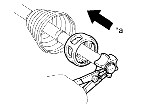
REMOVE FRONT AXLE INBOARD JOINT SET LH
-
Remove any old grease from the front axle inboard joint set LH.
-
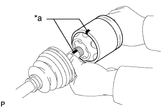
Text in Illustration *a Matchmark Place matchmarks on the front axle inboard joint set LH and outboard joint shaft.
Note
Do not use a punch to make the matchmarks.
-
Remove the front axle inboard joint set LH from the outboard joint shaft.
-
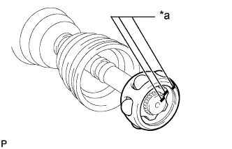
Text in Illustration *a Matchmark Place matchmarks on the outboard joint shaft, inner race and cage.
Note
Do not use a punch to make the matchmarks.
-
Remove the 6 balls.
-
Slide the cage to the outboard joint side.
-
Text in Illustration *a Outboard joint side Using a snap ring expander, remove the snap ring.
-
Using a brass bar and hammer, remove the inner race.
Note
Do not damage the inner race.
-
Remove the cage.
-
Remove the front No. 2 axle inboard joint boot setting clamp and front No. 1 axle inboard joint boot setting clamp, front axle inboard joint boot from the outboard joint shaft.
-
-
DISCONNECT FRONT NO. 1 AXLE OUTBOARD JOINT BOOT SETTING CLAMP
-
Using a side cutter, cut the front No. 1 axle outboard joint boot setting clamp and disconnect it.
-
-
DISCONNECT FRONT NO. 2 AXLE OUTBOARD JOINT BOOT SETTING CLAMP
-
Use the same procedure described for the front No. 1 axle outboard joint boot setting clamp.
-
-
REMOVE FRONT AXLE OUTBOARD JOINT BOOT
-
Remove any old grease from the front axle outboard joint boot.
-
Remove the front No. 2 axle outboard joint boot setting clamp and front axle outboard joint boot, front No. 1 axle outboard joint boot setting clamp from the outboard joint shaft.
-
-
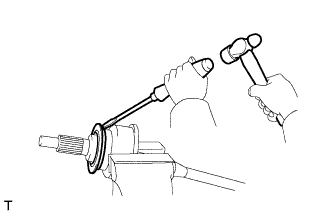
REMOVE DUST SEAL
-
Using a screwdriver and a hammer, remove the dust seal.
Note
Do not drop the outboard joint shaft.
-
-
REMOVE FRONT DRIVE SHAFT DUST COVER LH
-
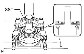
Using SST and a press, press out the front drive shaft dust cover LH.
- SST
- 09950-00020
Note
Do not drop the front axle inboard joint set LH.
-