REAR AXLE SHAFT INSTALLATION

-
INSTALL REAR AXLE SHAFT OIL SEAL LH
-
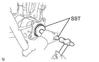
Using SST and a hammer, tap in a new oil seal.
Note
Do not allow foreign matter, etc. to contact the axle shaft housing hole.
- SST
- 09950-60020 ( 09951-00770 )
- 09950-70010 ( 09951-07150 )
-
-
INSTALL REAR AXLE SHAFT LH
-
Install the O-ring to the axle housing.
-
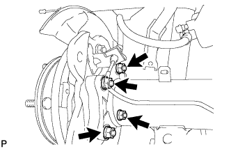
Install the rear axle shaft and parking brake plate with the 4 nuts.
- Torque:
- 60 N*m { 612 kgf*cm, 44 ft.*lbf }
-
-
CONNECT REAR SPEED SENSOR LH
-
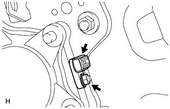
Install the speed sensor with the nut.
- Torque:
- 8.3 N*m { 85 kgf*cm, 73 in.*lbf }
Note
-
Make sure there are no pieces of iron or other foreign matter attached to the sensor tip.
-
While inserting the speed sensor into the knuckle hole, do not strike or damage the sensor tip.
-
After installing the speed sensor, make sure there is no clearance or foreign matter between the sensor stay part and the knuckle.
-
Make sure there is no foreign matter attached to the speed sensor rotor.
-
-
CONNECT NO. 3 PARKING BRAKE CABLE ASSEMBLY
-
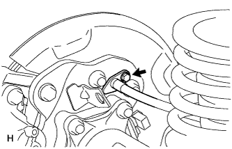
Connect the No. 3 parking brake cable with the bolt.
- Torque:
- 8.0 N*m { 82 kgf*cm, 71 in.*lbf }
-
-
INSTALL PARKING BRAKE SHOE LEVER SUB-ASSEMBLY LH
-
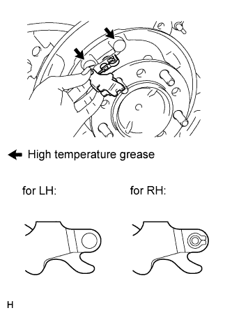
Apply high temperature grease to the parking brake anchor block.
-
Install the parking brake shoe lever to the No. 3 parking brake cable.
Note
Be carefully to distinguish between the parking brake shoe lever RH and LH.
-
-
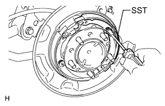
INSTALL NO. 2 PARKING BRAKE SHOE ASSEMBLY LH
-
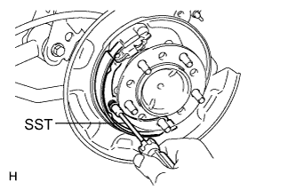
Using SST, install the No. 2 parking brake shoe with the shoe hold down spring pin, compression spring and shoe hold down spring cup.
- SST
- 09718-00011
-
-
INSTALL NO. 1 PARKING BRAKE SHOE ASSEMBLY LH
-
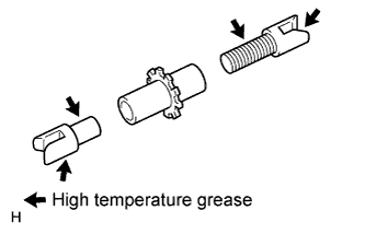
Apply high temperature grease to the thread and all joining areas of the parking brake shoe adjuster screw set.
-
Set the No. 1 parking brake shoe and shoe adjuster screw set in place.
-
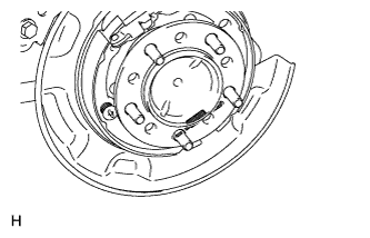
Connect the tension spring.
-
Using SST, install the shoe hold down spring pin, compression spring and shoe hold down spring cup.
- SST
- 09718-00011
-
-
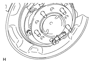
INSTALL PARKING BRAKE SHOE RETURN TENSION SPRING LH
-
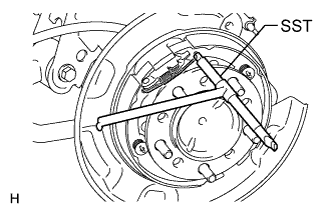
Using SST, install the shoe return spring.
- SST
- 09703-30011
-
-
CHECK PARKING BRAKE INSTALLATION
-
Check that each part is installed properly.
-
-
INSTALL REAR DISC LH
-
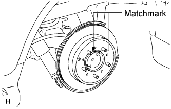
Align the matchmarks, and then install the rear disc.
Tech Tips
When replacing the rear disc with a new one, select the installation position where the rear disc has the minimum runout.
-
-
CONNECT REAR DISC BRAKE CYLINDER ASSEMBLY LH
-
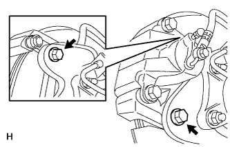
Connect the rear disc brake cylinder and install 2 new bolts.
- Torque:
- 95 N*m { 969 kgf*cm, 70 ft.*lbf }
Note
-
Do not twist the flexible hose.
-
Make sure that the bolts are free from damage and foreign matter.
-
Do not overtighten the bolts.
-
-
CONNECT REAR BRAKE FLEXIBLE HOSE
-
Set the flexible hose to the connecting point with the brake tube, and then install a new clip.
-
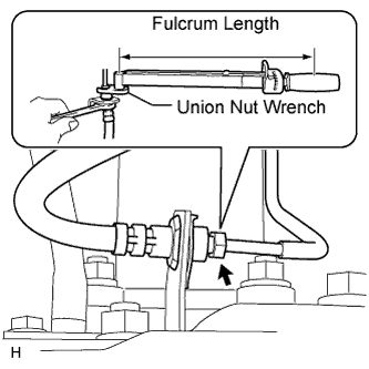
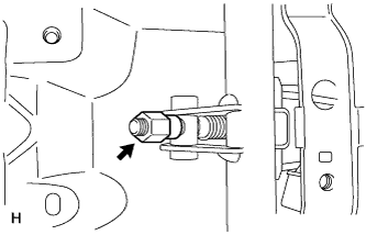
Using union nut wrench, connect the flexible hose to the brake tube while holding the flexible hose with a wrench.
- Torque:
- without union nut wrench
- 15 N*m { 155 kgf*cm, 11 ft.*lbf }
- with union nut wrench
- 14 N*m { 145 kgf*cm, 10 ft.*lbf }
Tech Tips
Use a torque wrench with a fulcrum length of 30 cm (11.8 in.).
Note
-
Do not bend or damage the brake tube.
-
Do not allow any foreign matter such as dirt and dust to enter the brake tube from the connecting point.
-
-
CONNECT CABLE TO NEGATIVE BATTERY TERMINAL
Note
When disconnecting the cable, some systems need to be initialized after the cable is reconnected Click here.
-
BLEED BRAKE LINE
-
Turn the ignition switch to ON.
-
Remove the brake master cylinder reservoir filler cap assembly.
-
Add brake fluid until the fluid level is between the MIN and MAX lines of the reservoir.
-
Repeatedly depress the brake pedal and bleed air from the bleeder plug of the front disc brake cylinder RH.
-
Repeat the step above until the air is completely bled, and then tighten the bleeder plug while depressing the brake pedal.
- Torque:
- 11 N*m { 110 kgf*cm, 8 ft.*lbf }
-
Bleed the air from the bleeder plug of the front disc brake cylinder LH using the same procedure as for the RH side.
-
With the brake pedal depressed, loosen the bleeder plug of the rear disc brake cylinder RH, continue to hold the brake pedal and allow brake fluid to be drained from the bleeder plug while the pump motor operates.
Tech Tips
-
Air is bled as the pump motor operates while the brake pedal is being depressed.
-
Be sure to release the brake pedal to stop the motor after approximately 100 seconds of continuous operation.
-
As brake fluid is continuously drained while the pump operates, it is not necessary to repeatedly depress the brake pedal.
-
-
When there is no more air in the brake fluid, tighten the bleeder plug, and then release the brake pedal.
- Torque:
- 11 N*m { 110 kgf*cm, 8 ft.*lbf }
-
Bleed the air from the bleeder plug of the rear disc brake cylinder LH using the same procedure as for the RH side.
-
Turn the ignition switch off.
-
Inspect for brake fluid leaks.
-
Check and adjust the brake fluid level Click here.
-
Clear the DTCs Click here.
-
-
INSPECT DIFFERENTIAL OIL
-
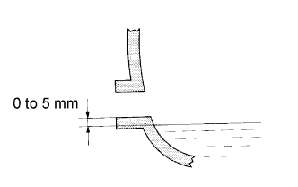
Add differential oil so that the oil level is between 0 to 5 mm (0 to 0.196 in.) from the bottom lip of the differential filler plug hole.
Note
-
Too much or too little oil will lead to differential problems.
-
After changing the oil, drive the vehicle and then check the oil level again.
Differential oil type and viscosity Toyota Genuine Differential gear oil LT 75W-85 GL-5 or equivalent Differential Oil Capacity Item Specified Condition Front Differential 1.85 to 1.95 liters (1.96 to 2.06 US qts., 1.63 to 1.71 Imp. qts.) Rear Differential 4.15 to 4.25 liters (4.39 to 4.49 US qts., 3.66 to 3.74 Imp. qts.) -
-
Front Differential:
-
Using a 10 mm hexagon wrench, install a new gasket and the filler plug.
- Torque:
- 39 N*m { 400 kgf*cm, 29 ft.*lbf }
-
Install the engine under cover Click here.
-
-
Rear Differential:
-
Install a new gasket and the filler plug.
- Torque:
- 49 N*m { 500 kgf*cm, 36 ft.*lbf }
-
-
-
INSPECT FOR DIFFERENTIAL OIL LEAK
-
CHECK PARKING BRAKE LEVER TRAVEL
-
Fully pull the parking brake lever to engage the parking brake.
-
Release the lever to disengage the parking brake.
-
Slowly pull the parking brake lever all the way, and count the number of clicks.
Standard Parking Brake Lever Travel when Pulled with a Force of 200 N (20 kgf, 45 lbf) 5 to 7 clicks If the parking brake lever travel is not as specified, adjust the parking brake shoe clearance and parking brake lever travel.
-
-
ADJUST PARKING BRAKE LEVER TRAVEL
-
Remove the console cup holder box sub-assembly Click here.
-
Completely release the parking brake lever.
-
Loosen the adjusting nut to completely release the parking brake cable.
-
Temporarily install the hub nuts.
-
Remove the hole plug.
-
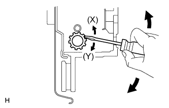
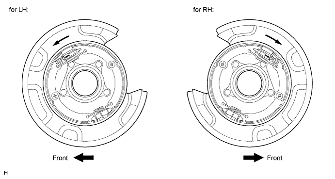
Insert an adjustment tool into the adjustment hole of the disc. Rotate the adjustment wheel in the "X" direction until the shoes are locked. Then rotate the adjustment wheel in the "Y" direction 8 notches.
-
Check that the disc can be rotated lightly. If not, rotate the adjustment wheel in the "Y" direction and check again.
-
Install the hole plug.
-
Remove the hub nuts.
-
Turn the adjusting nut until the parking brake lever travel becomes correct.
Standard Parking Brake Lever Travel when Pulled with a Force of 200 N (20 kgf, 45 lbf) 5 to 7 clicks -
Operate the parking brake lever 3 to 4 times, and check the parking brake lever travel.
Standard Parking Brake Lever Travel when Pulled with a Force of 200 N (20 kgf, 45 lbf) 5 to 7 clicks -
Check whether the parking brake drags or not.
-
When operating the parking brake lever, check that the brake warning light comes on.
Standard Condition The brake warning light always illuminates at the first click. -
Install the console cup holder box sub-assembly Click here.
-
-
CHECK SRS WARNING LIGHT
-
Check the SRS warning light Click here.
-
-
CHECK SPEED SENSOR SIGNAL
-
Check the speed sensor signal Click here.
-
-
INSTALL REAR WHEEL LH
- Torque:
- 131 N*m { 1336 kgf*cm, 97 ft.*lbf }