REAR AXLE HUB BOLT REPLACEMENT

Tech Tips
-
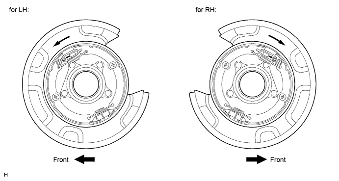
Use the same procedures for the LH side and RH side.
-
The procedures listed below are for the LH side.
-
REMOVE REAR WHEEL LH
-
DISCONNECT REAR DISC BRAKE CYLINDER ASSEMBLY LH
-
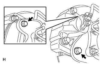
Remove the 2 bolts and disconnect the rear disc brake cylinder.
Note
-
Do not twist or bend the flexible hose.
-
Do not disconnect the flexible hose from the disc brake cylinder.
-
-
-
REMOVE REAR DISC LH
-
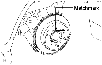
Put matchmarks on the rear disc and axle hub if planning to reuse the disc.
-
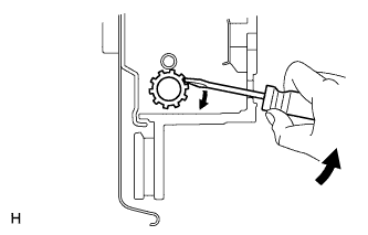
Turn the shoe adjuster as shown in the illustration until the disc turns freely, and then remove the disc.
-
-
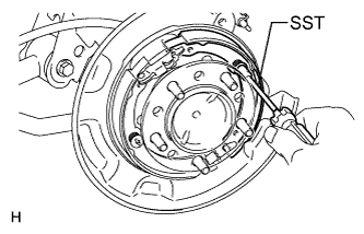
REMOVE PARKING BRAKE SHOE RETURN TENSION SPRING LH
-
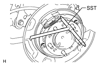
Using SST, remove the return spring.
- SST
- 09703-30011
-
-
REMOVE NO. 1 PARKING BRAKE SHOE ASSEMBLY LH
-
Using SST, remove the shoe hold down spring cup, compression spring and shoe hold down spring pin.
- SST
- 09718-00011
-
Disconnect the tension spring from the No. 1 parking brake shoe.
-
Remove the No. 1 parking brake shoe and shoe adjuster screw set.
-
-
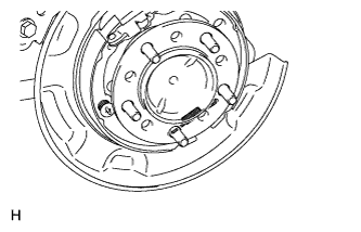
REMOVE NO. 2 PARKING BRAKE SHOE ASSEMBLY LH
-
Using SST, remove the shoe hold down spring cup, compression spring and shoe hold down spring pin.
- SST
- 09718-00011
-
Remove the No. 2 parking brake shoe.
-
-
REMOVE PARKING BRAKE SHOE LEVER SUB-ASSEMBLY LH
-
Disconnect the No. 3 parking brake cable from the parking brake shoe lever.
-
Remove the parking brake shoe lever.
-
-
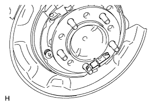
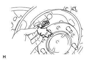
REMOVE REAR AXLE HUB BOLT LH
-
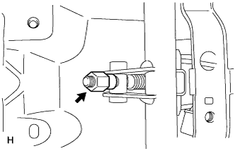
Using SST and a screwdriver or equivalent to hold the axle hub, remove the hub bolt.
- SST
- 09650-17011
Note
-
Do not deform the oil deflector.
-
Make sure to align the notch of SST with the flange of the oil deflector.
-
-
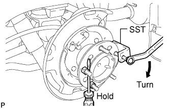
INSTALL REAR AXLE HUB BOLT LH
-
Temporarily install a washer and hub nut to a new hub bolt as shown in the illustration.
Note
Install a hub nut to prevent damage to the hub bolt.
-
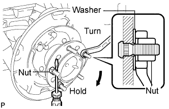
Using a screwdriver or equivalent to hold the hub, turn the hub nut until the bottom surface of the hub bolt head touches the axle hub.
-
Remove the washer and hub nut.
Note
Do not damage the threads of the hub bolt.
-
-
INSTALL PARKING BRAKE SHOE LEVER SUB-ASSEMBLY LH
-
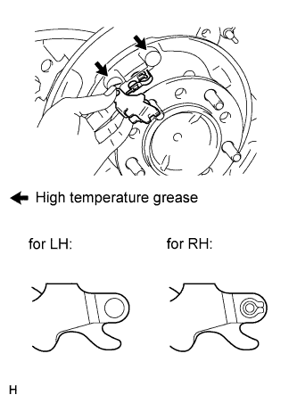
Apply high temperature grease to the parking brake anchor block.
-
Install the parking brake shoe lever to the No. 3 parking brake cable.
Note
Be carefully to distinguish between the parking brake shoe lever RH and LH.
-
-
INSTALL NO. 2 PARKING BRAKE SHOE ASSEMBLY LH
-
Using SST, install the No. 2 parking brake shoe with the shoe hold down spring pin, compression spring and shoe hold down spring cup.
- SST
- 09718-00011
-
-
INSTALL NO. 1 PARKING BRAKE SHOE ASSEMBLY LH
-
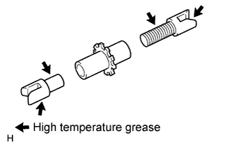
Apply high temperature grease to the thread and all joining areas of the parking brake shoe adjuster screw set.
-
Set the No. 1 parking brake shoe and shoe adjuster screw set in place.
-
Connect the tension spring.
-
Using SST, install the shoe hold down spring pin, compression spring and shoe hold down spring cup.
- SST
- 09718-00011
-
-
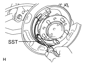
INSTALL PARKING BRAKE SHOE RETURN TENSION SPRING LH
-
Using SST, install the shoe return spring.
- SST
- 09703-30011
-
-
CHECK PARKING BRAKE INSTALLATION
-
Check that each part is installed properly.
-
-
INSTALL REAR DISC LH
-
Align the matchmarks, and then install the rear disc.
Tech Tips
When replacing the rear disc with a new one, select the installation position where the rear disc has the minimum runout.
-
-
CONNECT REAR DISC BRAKE CYLINDER ASSEMBLY LH
-
Connect the rear disc brake cylinder and install 2 new bolts.
- Torque:
- 95 N*m { 969 kgf*cm, 70 ft.*lbf }
Note
-
Do not twist the flexible hose.
-
Make sure that the bolts are free from damage and foreign matter.
-
Do not overtighten the bolts.
-
-
CHECK PARKING BRAKE LEVER TRAVEL
-
Fully pull the parking brake lever to engage the parking brake.
-
Release the lever to disengage the parking brake.
-
Slowly pull the parking brake lever all the way, and count the number of clicks.
Standard Parking Brake Lever Travel when Pulled with a Force of 200 N (20 kgf, 45 lbf) 5 to 7 clicks If the parking brake lever travel is not as specified, adjust the parking brake shoe clearance and parking brake lever travel.
-
-
ADJUST PARKING BRAKE LEVER TRAVEL
-
Remove the console cup holder box sub-assembly Click here.
-
Completely release the parking brake lever.
-
Loosen the adjusting nut to completely release the parking brake cable.
-
Temporarily install the hub nuts.
-
Remove the hole plug.
-
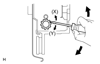
Insert an adjustment tool into the adjustment hole of the disc. Rotate the adjustment wheel in the "X" direction until the shoes are locked. Then rotate the adjustment wheel in the "Y" direction 8 notches.
-
Check that the disc can be rotated lightly. If not, rotate the adjustment wheel in the "Y" direction and check again.
-
Install the hole plug.
-
Remove the hub nuts.
-
Turn the adjusting nut until the parking brake lever travel becomes correct.
Standard Parking Brake Lever Travel when Pulled with a Force of 200 N (20 kgf, 45 lbf) 5 to 7 clicks -
Operate the parking brake lever 3 to 4 times, and check the parking brake lever travel.
Standard Parking Brake Lever Travel when Pulled with a Force of 200 N (20 kgf, 45 lbf) 5 to 7 clicks -
Check whether the parking brake drags or not.
-
When operating the parking brake lever, check that the brake warning light comes on.
Standard Condition The brake warning light always illuminates at the first click. -
Install the console cup holder box sub-assembly Click here.
-
-
INSTALL REAR WHEEL LH
- Torque:
- 131 N*m { 1336 kgf*cm, 97 ft.*lbf }