AUTOMATIC TRANSMISSION ASSEMBLY (for 3UR-FE) INSTALLATION

-
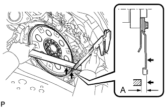
INSTALL TORQUE CONVERTER CLUTCH ASSEMBLY
-
Using a vernier caliper and straightedge, measure dimension A between the transmission and the end surface of the drive plate.
-
Install the torque converter to the transmission housing.
-
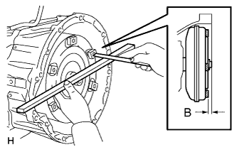
Using a vernier caliper and straightedge, measure dimension B shown in the illustration and check that B is more than A measured in the first step.
Standard distance B = A + 1.00 mm (0.0394 in.) or more
-
-
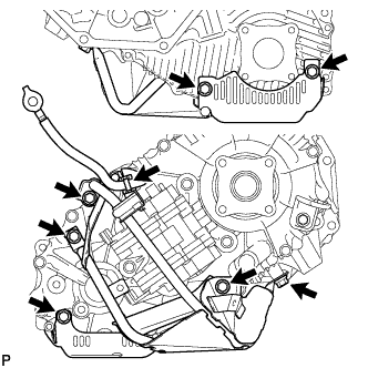
INSTALL WIRE HARNESS CLAMP BRACKET
-
Install the front bracket LH with the bolt.
- Torque:
- 8.0 N*m { 82 kgf*cm, 71 in.*lbf }
-
Install the rear bracket LH with the bolt.
- Torque:
- 29 N*m { 296 kgf*cm, 21 ft.*lbf }
-
Install the rear bracket RH with the bolt.
- Torque:
- 29 N*m { 296 kgf*cm, 21 ft.*lbf }
-
Install the front bracket RH with the bolt.
- Torque:
- 8.0 N*m { 82 kgf*cm, 71 in.*lbf }
-
Install the rear engine bracket with the bolt.
- Torque:
- 8.0 N*m { 82 kgf*cm, 71 in.*lbf }
-
-
INSTALL TRANSFER ASSEMBLY
-
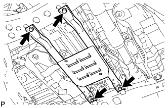
Install the transfer with the 8 bolts.
- Torque:
- 40 N*m { 408 kgf*cm, 30 ft.*lbf }
Note
Be careful not to damage the oil seal of the transfer adapter.
-
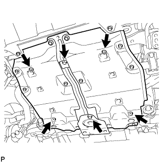
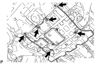
Install the transfer case lower protector with the 7 bolts.
- Torque:
- 14 N*m { 143 kgf*cm, 10 ft.*lbf }
-
Connect the clamp of grand cable to the transfer case lower protector.
-
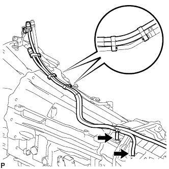
Attach the 3 breather hose clamps to connect the transfer breather hose to the automatic transmission breather tube.
-
-
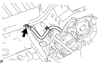
CONNECT BREATHER PLUG HOSE
-
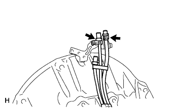
Connect the 2 breather plug hoses to the harness clamp bracket.
-
-
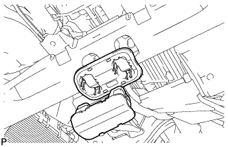
INSTALL TRANSMISSION OIL COOLER ASSEMBLY (w/o Air Cooled Transmission Oil Cooler)
-
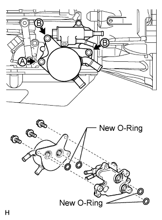
Coat 4 new O-rings with ATF.
-
Install the 4 O-rings, transmission oil thermostat and transmission oil cooler to the automatic transmission.
-
Temporarily install bolt A. Install the bolts labeled B and tighten them to the specified torque. Then tighten bolt A to the specified torque.
- Torque:
- 21 N*m { 214 kgf*cm, 15 ft.*lbf }
-
-
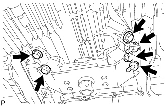
INSTALL AUTOMATIC TRANSMISSION ASSEMBLY
Note
Confirm that the 2 knock pins are attached to the transmission contact surface of the engine block before the installing the transmission.
-
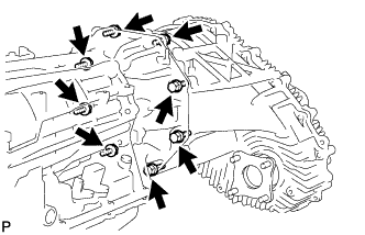
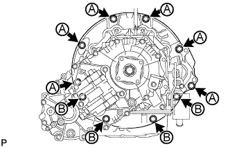
Install the transmission with the 10 bolts.
- Torque:
- for 17 mm head bolt A
- 71 N*m { 724 kgf*cm, 52 ft.*lbf }
- for 14 mm head bolt B
- 37 N*m { 377 kgf*cm, 27 ft.*lbf }
-
-
CONNECT TRANSMISSION OIL COOLER HOSE (w/o Air Cooled Transmission Oil Cooler)
-
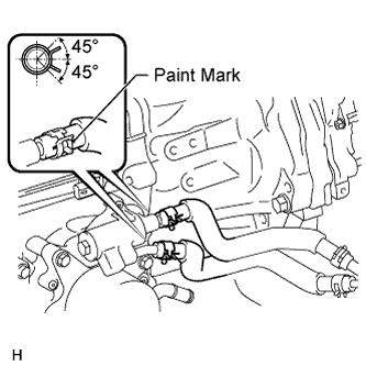
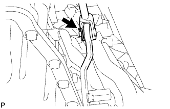
Connect the 2 transmission oil cooler hoses to the transmission oil thermostat.
Note
-
Make sure the pinching portion of each clip is facing the direction shown in the illustration.
-
Make sure the paint mark of each hose is facing outward.
-
-
-
CONNECT NO. 2 WATER BY-PASS PIPE (w/o Air Cooled Transmission Oil Cooler)
-
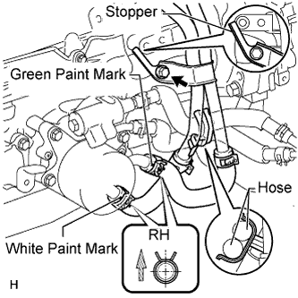
Connect the 2 water by-pass hoses with the 2 clips and install the water by-pass pipe with the bolt.
- Torque:
- 18 N*m { 184 kgf*cm, 13 ft.*lbf }
Note
-
Make sure the pinching portion of each clip is facing the direction shown in the illustration.
-
Make sure the paint mark of each hose is facing outward.
-
-
CONNECT TRANSMISSION OIL COOLER HOSE
-
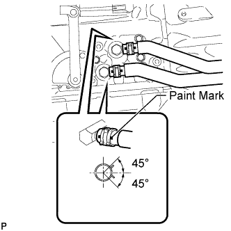
Connect the 2 transmission oil cooler hoses to the oil cooler tube union.
Note
-
Make sure the pinching portion of each clip is facing the direction shown in the illustration.
-
Make sure the paint mark of each hose is facing outward.
-
-
-
CONNECT WIRE HARNESS AND CONNECTOR
-
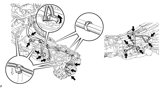
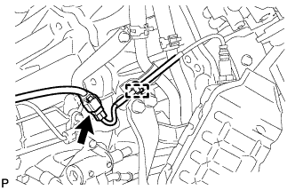
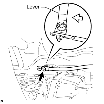
Connect the park/neutral position switch connector, 2 transmission wire connectors, 2 speed sensor connectors and 3 transfer control side connectors.
Tech Tips
Push up the lever until the claw of the transmission wire connector makes a connection sound.
-
Connect the 4 connector clamps and 6 harness clamps.
-
Connect the wire harness with the bolt.
- Torque:
- 8.0 N*m { 82 kgf*cm, 71 in.*lbf }
-
Tilt up the automatic transmission.
-
Connect the ground cable with the bolt.
- Torque:
- 8.4 N*m { 86 kgf*cm, 74 in.*lbf }
-
-
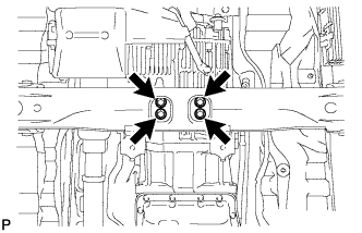
INSTALL REAR NO. 1 ENGINE MOUNTING INSULATOR
-
Install the rear engine mounting insulator to the transmission with the 4 bolts.
- Torque:
- 59 N*m { 602 kgf*cm, 44 ft.*lbf }
-
Install the engine mounting heat insulator with the 2 bolts.
- Torque:
- 12 N*m { 122 kgf*cm, 9 ft.*lbf }
-
-
INSTALL NO. 2 FRAME CROSSMEMBER SUB-ASSEMBLY
-
Install the frame crossmember to the rear engine mounting insulator with the 4 bolts.
- Torque:
- 37 N*m { 377 kgf*cm, 27 ft.*lbf }
-
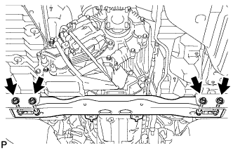
Install the frame crossmember to the frame with the 4 bolts and 4 nuts.
- Torque:
- 110 N*m { 1122 kgf*cm, 81 ft.*lbf }
-
Install the engine mounting hole cover.
-
-
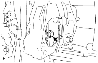
INSTALL DRIVE PLATE AND TORQUE CONVERTER CLUTCH SETTING BOLT
-
Turn the crankshaft to gain access to the installation locations of the 6 bolts and install the bolts while holding the crankshaft pulley set bolt with a wrench.
- Torque:
- 53 N*m { 535 kgf*cm, 39 ft.*lbf }
Note
First install the black colored bolt and then the remaining 5 bolts.
-
Install the flywheel housing side cover.
-
-
INSTALL STARTER ASSEMBLY
-
Install the flywheel housing side cover.
-
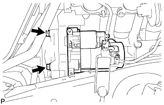
Install the starter with the 2 bolts.
- Torque:
- 37 N*m { 377 kgf*cm, 27 ft.*lbf }
-
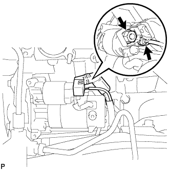
Install the starter wire with the nut.
- Torque:
- 9.8 N*m { 100 kgf*cm, 87 in.*lbf }
-
Connect the starter connector.
-
-
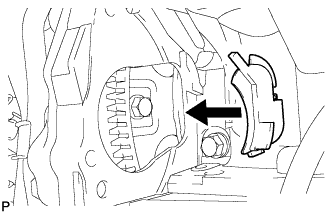
INSTALL STARTER COVER
-
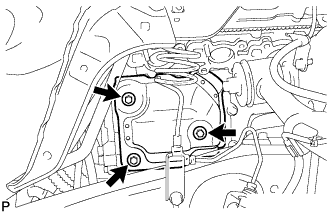
Install the starter cover with the 3 bolts.
- Torque:
- 12 N*m { 122 kgf*cm, 9 ft.*lbf }
-
-
INSTALL EXHAUST MANIFOLD SUB-ASSEMBLY RH
-
w/ Secondary Air Injection System:
-
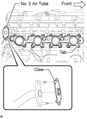
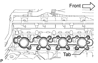
Install a new gasket to the cylinder head and a new gasket to the No. 2 air tube.
Tech Tips
-
Install the exhaust manifold gasket with the gasket tab facing toward the front of the engine.
-
Install the air tube gasket with the gasket claws facing the tube side.
-
-
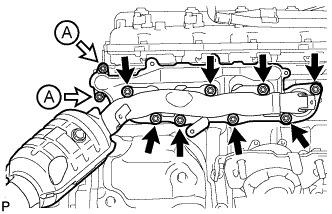
Temporarily install the exhaust manifold with the 2 nuts labeled A and 8 new nuts.
-
Uniformly tighten the nuts that are not labeled A, and then tighten the 2 nuts labeled A.
- Torque:
- for nut A
- 10 N*m { 102 kgf*cm, 7 ft.*lbf }
- except nut A
- 30 N*m { 306 kgf*cm, 22 ft.*lbf }
-
-
w/o Secondary Air Injection System:
-
Install a new gasket to the cylinder head.
Tech Tips
Install the exhaust manifold gasket with the gasket tab facing toward the front of the engine.
-
Temporarily install the exhaust manifold with the 8 new nuts.
-
Uniformly tighten the 8 nuts.
- Torque:
- 30 N*m { 306 kgf*cm, 22 ft.*lbf }
-
-
Attach the wire harness clamp to the bracket and connect the connector.
-
-
INSTALL NO. 1 EXHAUST MANIFOLD HEAT INSULATOR
-
Install the heat insulator with the 3 bolts.
- Torque:
- 10 N*m { 102 kgf*cm, 7 ft.*lbf }
-
-
INSTALL ENGINE OIL LEVEL DIPSTICK GUIDE
-
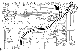
Apply a light coat of engine oil to a new O-ring.
-
Install the O-ring to the guide.
-
Install the dipstick guide with the bolt.
- Torque:
- 10 N*m { 102 kgf*cm, 7 ft.*lbf }
-
Install the dipstick.
-
-
INSTALL NO. 2 MANIFOLD STAY
-
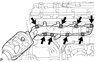
Temporarily install the manifold stay with the 3 bolts.
-
Tighten the 3 bolts in the order shown in the illustration.
- Torque:
- 40 N*m { 408 kgf*cm, 30 ft.*lbf }
-
-
INSTALL NO. 1 MANIFOLD STAY
-
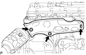
Temporarily install the manifold stay with the 3 bolts.
-
Tighten the 3 bolts in the order shown in the illustration.
- Torque:
- 40 N*m { 408 kgf*cm, 30 ft.*lbf }
-
-
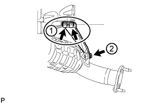
INSTALL FRONT EXHAUST PIPE ASSEMBLY
-
Install a new gasket and the front exhaust pipe to the exhaust manifold RH with 2 new nuts.
- Torque:
- 54 N*m { 551 kgf*cm, 40 ft.*lbf }
-
Install the wire harness clamp bracket of the oxygen sensor to the transmission with the bolt.
- Torque:
- 29 N*m { 296 kgf*cm, 21 ft.*lbf }
-
Connect the heated oxygen sensor connector.
-
-
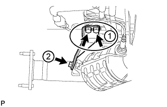
INSTALL FRONT NO. 2 EXHAUST PIPE ASSEMBLY
-
Install a new gasket and the front No. 2 exhaust pipe to the exhaust manifold LH with 2 new nuts.
- Torque:
- 54 N*m { 551 kgf*cm, 40 ft.*lbf }
-
Install the wire harness clamp bracket of the oxygen sensor to the transmission with the bolt.
- Torque:
- 29 N*m { 296 kgf*cm, 21 ft.*lbf }
-
Connect the heated oxygen sensor connector.
-
-
INSTALL CENTER EXHAUST PIPE ASSEMBLY
-
Install 2 new gaskets to the front exhaust pipe and front No. 2 exhaust pipe.
-
Install the center exhaust pipe to the 3 exhaust pipe supports, and then install the 4 bolts.
- Torque:
- 48 N*m { 489 kgf*cm, 35 ft.*lbf }
-
-
INSTALL TAILPIPE ASSEMBLY
-
Install the tailpipe to the 2 exhaust pipe supports.
-
Install a new gasket to the center exhaust pipe.
-
Connect the tailpipe to the center exhaust pipe.
-
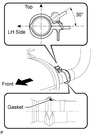
Attach a new clamp to the tailpipe and center exhaust pipe. Then install the bolt to the clamp.
- Torque:
- 32 N*m { 326 kgf*cm, 24 ft.*lbf }
Tech Tips
Install the clamp within the angle range shown in the illustration.
-
-
INSTALL PROPELLER SHAFT ASSEMBLY
-
Install the propeller shaft Click here.
-
-
INSTALL FRONT PROPELLER SHAFT ASSEMBLY
-
Install the front propeller shaft Click here.
-
-
CONNECT FLOOR SHIFT GEAR SHIFTING ROD SUB-ASSEMBLY
-
Connect the gear shifting rod to the transmission control shaft lever RH with the pin and a new clip.
-
-
CONNECT CABLE TO NEGATIVE BATTERY TERMINAL
Note
When disconnecting the cable, some systems need to be initialized after the cable is reconnected Click here.
-
ADD AUTOMATIC TRANSMISSION FLUID
-
Add automatic transmission fluid Click here.
-
-
ADD ENGINE COOLANT
-
Add engine coolant.
Standard Capacity Item Specified Condition with transmission oil cooler 16.7 liters (17.6 US qts, 14.7 Imp. qts) without transmission oil cooler 16.2 liters (17.1 US qts, 14.3 Imp. qts) Note
Do not substitute plain water for engine coolant.
Tech Tips
TOYOTA vehicles are filled with TOYOTA SLLC at the factory. In order to avoid damage to the engine cooling system and other technical problems, only use TOYOTA SLLC or similar high quality ethylene glycol based non-silicate, non-amine, non-nitrite, non-borate coolant with long-life hybrid organic acid technology (coolant with long-life hybrid organic acid technology consists of a combination of low phosphates and organic acids).
-
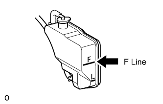
Slowly pour coolant into the radiator reservoir until it reaches the F line.
-
Install the reservoir cap.
-
Press the No. 1 and No. 2 radiator hoses several times by hand, and then check the coolant level. If the coolant level is low, add coolant.
-
Install the radiator cap.
-
Start the engine and warm it up until the thermostat opens.
Note
Switch off the A/C.
-
Maintain the engine speed at 2000 to 2500 rpm.
Note
-
Make sure that the radiator reservoir still has some coolant in it.
-
Pay attention to the needle of the water temperature meter. Make sure that the needle does not show an abnormally high temperature.
-
If there is not enough coolant, the engine may burn out or overheat.
-
Immediately after starting the engine, if the radiator reservoir does not have any coolant, perform the following: 1) stop the engine, 2) wait until the coolant has cooled down, and 3) add coolant until the coolant is filled to the F line.
-
Run the engine at 2000 rpm until the coolant level has stabilized.
-
-
Press the No. 1 and No. 2 radiator hoses several times by hand to bleed air.
CAUTION:
-
Wear protective gloves.
-
Be careful as the radiator hoses are hot.
-
Keep your hands away from the fan.
-
-
Stop the engine, and wait until the engine coolant cools down to ambient temperature.
CAUTION:
Do not remove the radiator cap while the engine and radiator are still hot. Pressurized, hot engine coolant and steam may be released and cause serious burns.
-
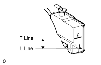
Check that the coolant level is between the F and L lines.
If the coolant level is below the L line, repeat all of the procedures above.
If the coolant level is above the F line, drain coolant so that the coolant level is between the F and L lines.
-
-
INSPECT FOR ENGINE COOLANT LEAK
-
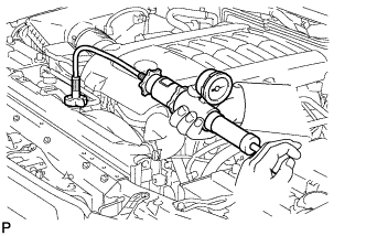
Fill the radiator with coolant and attach a radiator cap tester.
-
Warm up the engine.
-
Using the radiator cap tester, increase the pressure inside the radiator to 123 kPa (1.3 kgf/cm2, 18 psi), and check that the pressure does not drop.
If the pressure drops, check the hoses, radiator and water pump for leaks. If no external leaks are found, check the heater core, cylinder block and head.
-
-
INSPECT SHIFT LEVER POSITION
-
When moving the shift lever from P to R with the engine switch on (IG) and the brake pedal depressed, make sure that it moves smoothly and correctly into position.
-
Check that the shift lever does not stop when moving the shift lever from R to P, and check that the shift lever does not stick when moving the shift lever from D to S.
-
Start the engine and make sure that the vehicle moves forward after moving the shift lever from N to D and moves rearward after moving the shift lever to R.
If there are problems during the above inspections, perform the adjustment using the following procedures.
-
Move the shift lever to N
-
Loosen the nut of the floor shift gear shifting rod. Then, with the lever of the floor shift assembly lightly pushed towards the rear of the vehicle, tighten the nut.
- Torque:
- 13 N*m { 133 kgf*cm, 10 ft.*lbf }
-
-
-
INSPECT FOR EXHAUST GAS LEAK
-
INSTALL UPPER RADIATOR SUPPORT SEAL
-
Attach the 14 clips to install the upper radiator seal.
-
-
INSTALL ENGINE ROOM SIDE COVER RH
-
Install the engine room side cover RH with the 7 clips.
-
-
INSTALL ENGINE ROOM SIDE COVER LH
-
Install the engine room side cover LH with the 7 clips.
-
-
INSTALL OIL PAN PROTECTOR ASSEMBLY
-
Install the oil pan protector with the 4 bolts.
- Torque:
- 63 N*m { 642 kgf*cm, 46 ft.*lbf }
-
-
INSTALL NO. 1 ENGINE UNDER COVER
-
Install the under cover with the 6 bolts.
- Torque:
- 29 N*m { 296 kgf*cm, 21 ft.*lbf }
-
-
INSTALL NO. 2 ENGINE UNDER COVER
-
Install the under cover with the 6 bolts.
- Torque:
- 29 N*m { 296 kgf*cm, 21 ft.*lbf }
-
-
INSTALL FRONT FENDER SPLASH SHIELD SUB-ASSEMBLY LH
-
Push in the clip to install the front fender splash shield sub-assembly LH.
-
Install the 3 bolts and 2 screws.
-
-
INSTALL FRONT FENDER SPLASH SHIELD SUB-ASSEMBLY RH
Tech Tips
Use the same procedure described for the LH side.
-
RESET MEMORY
-
Perform the Reset Memory procedures (A/T initialization) Click here.
-