OIL COOLER INSTALLATION

-
INSTALL OIL COOLER ASSEMBLY (w/ Air Cooled Transmission Oil Cooler)
-
Connect the oil cooler inlet hose and outlet hose.
-
Install the rear transmission oil cooler air duct with the 4 bolts, and then install the air cooled oil cooler tube to the transmission oil cooler air duct with the bolt.
- Torque:
- 4.9 N*m { 50 kgf*cm, 43 in.*lbf }
-
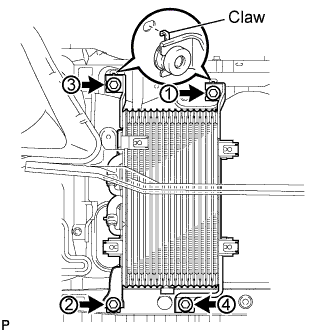
Temporarily put the oil cooler on the radiator support.
Note
Securely attach the 2 claws of the oil cooler into the holes of the radiator support.
-
Install the 4 bolts in the sequence shown in the illustration.
- Torque:
- 12 N*m { 122 kgf*cm, 9 ft.*lbf }
-
-
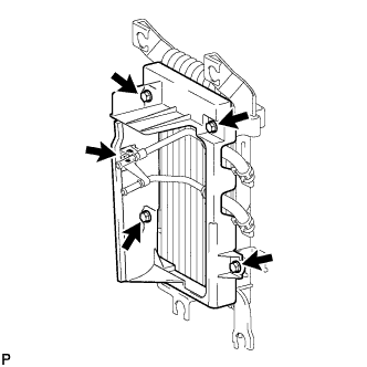
INSTALL TRANSMISSION OIL COOLER AIR DUCT (w/ Air Cooled Transmission Oil Cooler)
-
Install the oil cooler air duct with the 4 bolts in the sequence shown in the illustration.
- Torque:
- 4.9 N*m { 50 kgf*cm, 43 in.*lbf }
-
-
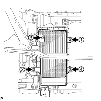
INSTALL OIL COOLER TUBE
-
Temporarily install the oil cooler tube to the fan shroud with bolt A. Install bolt B and tighten it to the specified torque. Then tighten bolt A to the specified torque.
- Torque:
- 5.0 N*m { 51 kgf*cm, 44 in.*lbf }
-
-
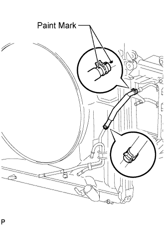
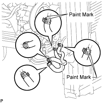
CONNECT INLET NO. 4 OIL COOLER HOSE (w/ Air Cooled Transmission Oil Cooler)
-
Connect the inlet oil cooler hose as shown in the illustration.
Note
Make sure the pinching portion of each clip is facing the direction shown in the illustration and the paint marks are aligned as shown in the illustration.
-
-
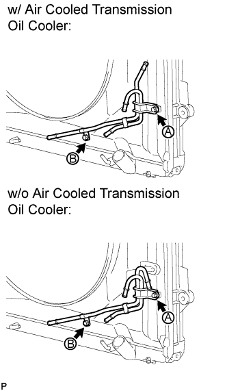
CONNECT INLET NO. 2 OIL COOLER HOSE AND INLET NO. 3 OIL COOLER HOSE
-
Connect the 2 inlet oil cooler hoses as shown in the illustration.
Note
Make sure the pinching portion of each clip is facing the direction shown in the illustration.
-
-
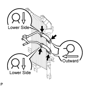
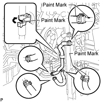
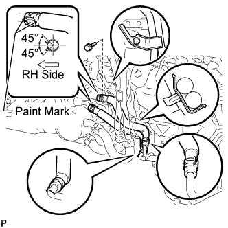
CONNECT INLET NO. 1 OIL COOLER HOSE AND OUTLET NO. 1 OIL COOLER HOSE
-
w/ Air Cooled Transmission Oil Cooler:
-
Connect the 2 oil cooler hoses as shown in the illustration.
Note
Make sure the pinching portion of each clip is facing the direction shown in the illustration and the paint marks are aligned as shown in the illustration.
-
Pass the hose through the flexible hose clamp and close the clamp shown in the illustration.
-
-
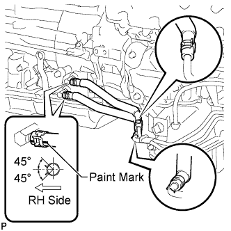
w/o Air Cooled Transmission Oil Cooler:
-
Connect the 2 oil cooler hoses as shown in the illustration.
Note
Make sure the pinching portion of each clip is facing the direction shown in the illustration and the paint marks are aligned as shown in the illustration.
-
-
-
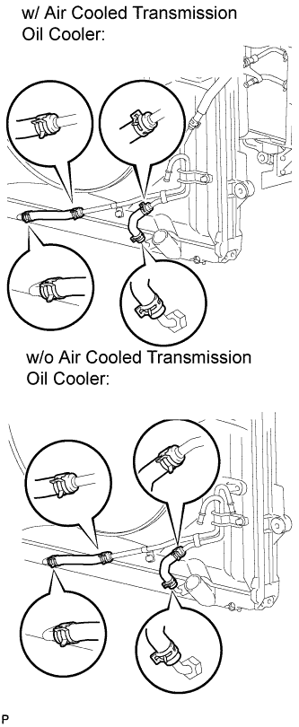
CONNECT TRANSMISSION OIL COOLER HOSE (w/o Air Cooled Transmission Oil Cooler)
-
Connect the 2 transmission oil cooler hoses as shown in the illustration, and then install the water by-pass pipe with the bolt.
- Torque:
- 18 N*m { 184 kgf*cm, 13 ft.*lbf }
Note
Make sure the pinching portion of each clip is facing the direction shown in the illustration.
-
-
CONNECT TRANSMISSION OIL COOLER HOSE (w/ Air Cooled Transmission Oil Cooler)
-
Connect the 2 transmission oil cooler hoses as shown in the illustration.
Note
Make sure the pinching portion of each clip is facing the direction shown in the illustration.
-
-
ADD AUTOMATIC TRANSMISSION FLUID
-
Add automatic transmission fluid Click here.
-
-
INSTALL FRONT FENDER APRON SEAL REAR RH
-
Install the front fender apron trim packing C with the 4 clips.
-
-
INSTALL FRONT FENDER APRON SEAL FRONT RH
-
Install the front fender apron trim packing A with the 3 clips.
-
-
INSTALL FRONT BUMPER ASSEMBLY (w/ Air Cooled Transmission Oil Cooler)
-
Install the front bumper Click here.
-
-
INSTALL NO. 1 ENGINE UNDER COVER
-
Install the No. 1 engine under cover sub-assembly with the 10 bolts.
- Torque:
- 29 N*m { 296 kgf*cm, 21 ft.*lbf }
-
-
INSTALL NO. 2 ENGINE UNDER COVER
-
Install the No. 2 engine under cover with the 2 bolts.
- Torque:
- 29 N*m { 296 kgf*cm, 21 ft.*lbf }
-
-
INSTALL FRONT FENDER SPLASH SHIELD SUB-ASSEMBLY LH
-
Push in the clip to install the front fender splash shield sub-assembly LH.
-
Install the 3 bolts and 2 screws.
-
-
INSTALL FRONT FENDER SPLASH SHIELD SUB-ASSEMBLY RH
Tech Tips
Use the same procedure described for the LH side.