TIRE PRESSURE WARNING SYSTEM TERMINALS OF ECU

-
CHECK TIRE PRESSURE WARNING ECU AND RECEIVER
-
Disconnect the tire pressure warning ECU and receiver L63 connector and measure the voltage and resistance on the wire harness side.

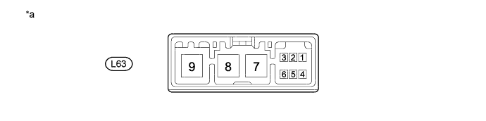
Text in Illustration *a Front view of wire harness connector
(to Tire Pressure Warning ECU and Receiver)
- - Terminal No. (Symbol) Wiring Color Terminal Description Condition Specified Condition L63-1 (IG1) - L63-4 (GN1) B - G IG power source Engine switch on (IG) 10 to 16 V L63-4 (GN1) - Body ground G - Body ground Ground Always Below 1 Ω -
Connect the tire pressure warning ECU and receiver L63 connector.
-
Measure the voltage according to the value(s) in the table below. If the result is not as specified, the ECU may have a malfunction.
Tech Tips
Inspect the connectors from the back side while the connectors are connected.
Text in Illustration *a Component with harness connected
(Tire Pressure Warning ECU and Receiver)
- - Terminal No. (Symbol) Wiring Color Terminal Description Condition Specified Condition L63-2 (CS1) - L63-4 (GN1) R - G Tire pressure warning reset switch
-
Engine switch on (IG)
-
Tire pressure warning reset switch ON
Below 2.4 V
-
Engine switch on (IG)
-
Tire pressure warning reset switch OFF
8 to 15 V -
-