REAR UPPER ARM INSTALLATION

Tech Tips
-
Use the same procedures for the RH side and LH side.
-
The procedures listed below are for the LH side.
-
A bolt without a torque specification is shown in the standard bolt chart Click here.
-
TEMPORARILY INSTALL REAR UPPER CONTROL ARM ASSEMBLY LH
-
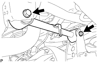
Temporarily install the rear upper control arm and 2 washers with the 2 bolts and 2 nuts.
-
-
STABILIZE SUSPENSION
-
Install the rear wheels.
- Torque:
- 131 N*m { 1336 kgf*cm, 97 ft.*lbf }
-
Lower the vehicle.
-
Press down on the vehicle several times to stabilize the suspension.
-
-
TIGHTEN REAR UPPER CONTROL ARM ASSEMBLY LH
-
Tighten the 2 nuts.
- Torque:
- 150 N*m { 1530 kgf*cm, 111 ft.*lbf }
Note
Perform this procedure with all 4 wheels on the ground.
-
-
INSTALL UPPER ARM BUSH HEAT INSULATOR
-
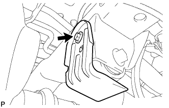
Install the upper arm bush heat insulator with the bolt.
- Torque:
- 18 N*m { 184 kgf*cm, 13 ft.*lbf }
-
-
CONNECT SPEED SENSOR WIRE HARNESS
-
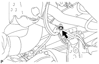
Connect the speed sensor wire harness with the bolt.
- Torque:
- 13 N*m { 127 kgf*cm, 9 ft.*lbf }
-
-
INSTALL REAR HEIGHT CONTROL SENSOR SUB-ASSEMBLY LH
-
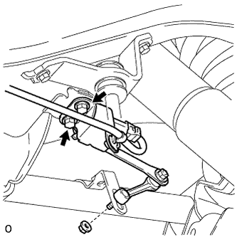
Install the sensor with the 2 bolts and nut.
- Torque:
- for bolt
- 13 N*m { 127 kgf*cm, 9 ft.*lbf }
- for nut
- 5.6 N*m { 57 kgf*cm, 50 in.*lbf }
-
Connect the connector and 2 clamps.
-
-
CONNECT CABLE TO NEGATIVE BATTERY TERMINAL
Note
When disconnecting the cable, some systems need to be initialized after the cable is reconnected Click here.
-
PERFORM VEHICLE OFF SET CALIBRATION
-
Perform the vehicle off set calibration Click here.
-
-
ADJUST REAR HEIGHT CONTROL SENSOR SUB-ASSEMBLY LH
Note
-
Make adjustments from the link that deviates the most from the specified vehicle height value.
-
When the front and rear are at the same level, make adjustments from the front first.
-
If adjustment cannot be completed through the vehicle height offset calibration, adjust the sensor link using the following procedure.
-
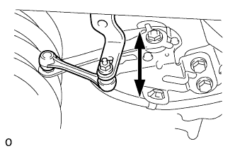
Loosen the nut and adjust the link installation position by moving the height control sensor link up or down in the long hole of the bracket.
Tech Tips
When the link is moved 1 mm (0.0394 in.), the vehicle height changes by approximately 2 mm (0.0787 in.).
-
Tighten the nut of the height control sensor link.
- Torque:
- 5.6 N*m { 57 kgf*cm, 50 in.*lbf }
-
-
ADJUST HEADLIGHT ASSEMBLY
-
Adjust the headlight assembly Click here.
-