REAR SHOCK ABSORBER INSTALLATION

Tech Tips
-
Use the same procedures for the RH side and LH side.
-
The procedures listed below are for the LH side.
-
A bolt without a torque specification is shown in the standard bolt chart Click here.
-
TEMPORARILY INSTALL REAR SHOCK ABSORBER ASSEMBLY LH
-
Install the lower bracket to the shock absorber.
-
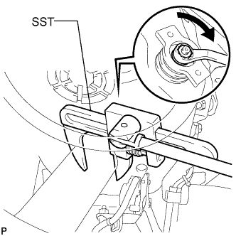
Using SST, hold the rear shock absorber in place.
- SST
- 09922-10010
-
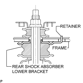
Temporarily install the rear shock absorber and upper bracket with the nut.
Note
Make sure the absorber retainer claw is securely inserted into the frame hole.
-
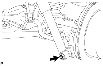
Temporarily install the lower side of the shock absorber with the bolt.
-
-
TEMPORARILY INSTALL REAR SHOCK ABSORBER ASSEMBLY RH
-
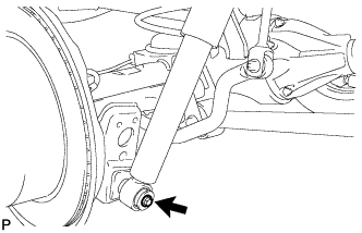
Temporarily install the lower side of the shock absorber with the bolt.
-
-
TEMPORARILY INSTALL REAR LATERAL CONTROL ROD ASSEMBLY
-
Temporarily install the lateral control rod with the nut and bolt.
-
-
STABILIZE SUSPENSION
-
Install the rear wheels.
- Torque:
- 131 N*m { 1336 kgf*cm, 97 ft.*lbf }
-
Lower the vehicle.
-
Press down on the vehicle several times to stabilize the suspension.
-
-
TIGHTEN REAR SHOCK ABSORBER ASSEMBLY LH
-
Tighten the bolt and nut.
- Torque:
- for Nut
- 53 N*m { 540 kgf*cm, 39 ft.*lbf }
- for Bolt
- 98 N*m { 999 kgf*cm, 72 ft.*lbf }
Note
Perform this procedure with all 4 wheels on the ground.
-
-
TIGHTEN REAR SHOCK ABSORBER ASSEMBLY RH
-
Tighten the bolt and nut.
- Torque:
- 98 N*m { 999 kgf*cm, 72 ft.*lbf }
Note
Perform this procedure with all 4 wheels on the ground.
-
-
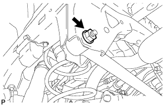
CONNECT NO. 4 SUSPENSION CONTROL PRESSURE HOSE
-
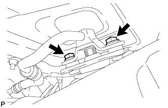
Install the pressure hose with the 2 bolts.
- Torque:
- 18 N*m { 184 kgf*cm, 13 ft.*lbf }
-
-
TIGHTEN REAR LATERAL CONTROL ROD ASSEMBLY
-
Tighten the nut.
- Torque:
- 150 N*m { 1530 kgf*cm, 111 ft.*lbf }
Note
Perform this procedure with all 4 wheels on the ground.
-
-
BLEED AIR FROM SUSPENSION FLUID
-
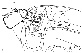
With the engine stopped, fill the reservoir tank with fluid.
Note
When the engine starts, the pump operates and fluid is supplied to each cylinder from the reservoir tank. Therefore, add the necessary amount of fluid so that the reservoir tank does not become empty.
Tech Tips
At this point, the vehicle height is low because the pressure of the cylinders is low.
-
With the vehicle on a level surface, start the engine and set the vehicle height to NORMAL with the suspension control switch.
-
When the vehicle height becomes NORMAL and the pump stops, stop the engine.
-
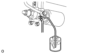
Connect a hose to the bleeder plug of the front left side or right side control valve, then loosen the bleeder plug.
CAUTION:
Be careful when loosening the control valve bleeder plug because the front vehicle height drops rapidly.
-
After the fluid containing air stops coming out, retighten the bleeder plug.
- Torque:
- 8.3 N*m { 85 kgf*cm, 73 in.*lbf }
Tech Tips
If the procedures are performed for the first time on the left side, perform the procedures on the right side for the second time.
-
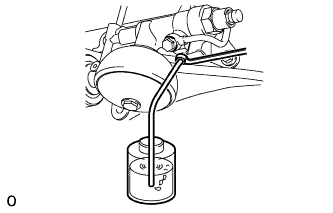
Connect a hose to the bleeder plug of the rear left side or right side control valve, then loosen the bleeder plug.
CAUTION:
Be careful when loosening the control valve bleeder plug because the rear vehicle height drops rapidly.
-
After the fluid containing air stops coming out, retighten the bleeder plug.
- Torque:
- 8.3 N*m { 85 kgf*cm, 73 in.*lbf }
Tech Tips
If the procedures are performed for the first time on the left side, perform the procedures on the right side for the second time.
-
Repeat the previous 4 procedures until the fluid containing air stops coming out.
-
-
CHECK FLUID LEVEL IN RESERVOIR
-
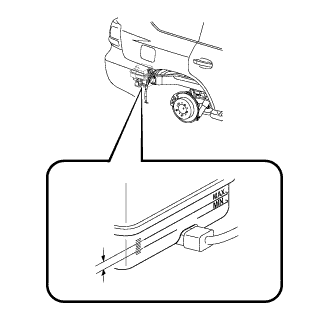
With the vehicle empty, after setting the vehicle height to NORMAL from LO, check the indicator to make sure the vehicle height is NORMAL and check that the fluid level in the reservoir tank is within the specified range (MAX, MIN).
Tech Tips
After changing the vehicle height from LO to NORMAL, do not stop the engine for 25 seconds because the pressure control for the main accumulator is operating. After that, check the fluid level.
-
-
INSPECT FOR SUSPENSION FLUID LEAK
-
Check the torque value of the rear No. 5 height control tube union nuts.
- Torque:
- without union nut wrench
- 15 N*m { 155 kgf*cm, 11 ft.*lbf }
- with union nut wrench
- 14 N*m { 143 kgf*cm, 10 ft.*lbf }
Tech Tips
-
Use a torque wrench with a fulcrum length of 300 mm (11.8 in.).
-
The torque value for use with a union nut wrench is effective when the union nut wrench is parallel to the torque wrench.
-
Check for fluid leakage from the parts and connections.
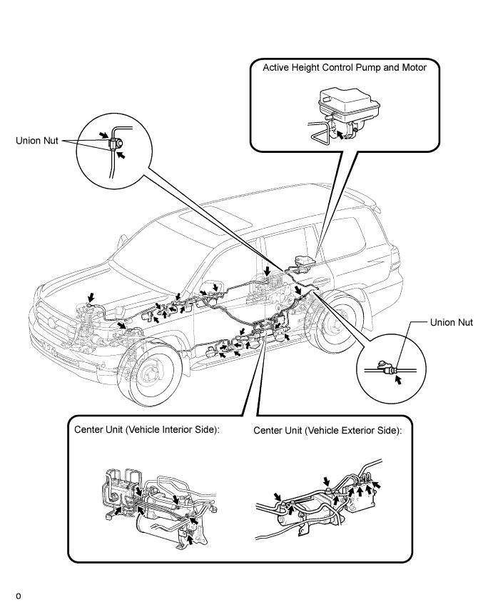
Tech Tips
For union nuts and union bolts not shown in the illustration, refer to the installation procedures for each title.
-
-
CONNECT NO. 3 PARKING BRAKE CABLE ASSEMBLY
-
Connect the No. 3 parking brake cable with the bolt.
- Torque:
- 13 N*m { 127 kgf*cm, 9 ft.*lbf }
-
-
CONNECT NO. 2 PARKING BRAKE CABLE ASSEMBLY
-
Connect the No. 2 parking brake cable with the bolt.
- Torque:
- 13 N*m { 127 kgf*cm, 9 ft.*lbf }
-
-
CONNECT REAR AXLE BREATHER HOSE SUB-ASSEMBLY
-
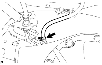
Connect the breather hose to the rear axle housing.
Note
Make sure the breather hose paint mark and claw of the clip are facing towards the front of the vehicle.
-