FRONT LOWER SUSPENSION ARM INSTALLATION

Tech Tips
-
Use the same procedures for the RH side and LH side.
-
The procedures listed below are for the LH side.
-
A bolt without a torque specification is shown in the standard bolt chart Click here.
-
TEMPORARILY INSTALL FRONT NO. 1 SUSPENSION ARM LOWER SUB-ASSEMBLY LH
-
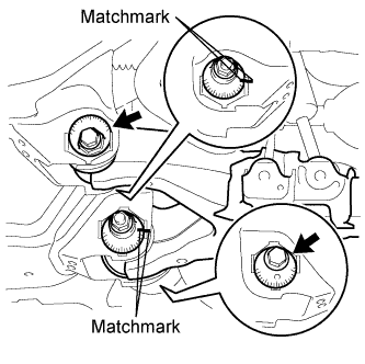
Temporarily install the lower suspension arm, camber adjusting cam, No. 2 camber adjusting cam, No. 2 suspension toe adjusting plate, toe adjusting cam and washer with the bolt and nut.
-
Align the matchmarks on the No. 2 camber adjusting cam and No. 2 suspension toe adjusting plate with the matchmarks on the vehicle body. Tighten the bolt and nut.
Tech Tips
The bolt and nut will be tightened to the torque specification in the "Tighten Front No. 1 Suspension Arm Lower Sub-assembly LH" procedure.
-
-
CONNECT FRONT LOWER BALL JOINT ATTACHMENT LH
-
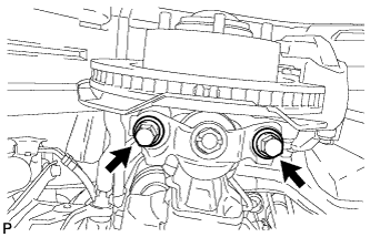
Connect the attachment to the steering knuckle with the 2 bolts.
- Torque:
- 300 N*m { 3059 kgf*cm, 221 ft.*lbf }
-
-
CONNECT FRONT SHOCK ABSORBER WITH COIL SPRING LH

-
Connect the shock absorber with the bolt and nut.
-
-
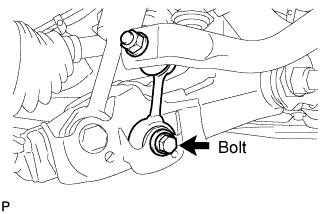
TEMPORARILY INSTALL FRONT STABILIZER LINK ASSEMBLY LH
-
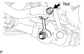
Temporarily install the stabilizer link with the nut and bolt.
-
Tighten the nut.
- Torque:
- 128 N*m { 1305 kgf*cm, 94 ft.*lbf }
-
-
TEMPORARILY INSTALL FRONT STABILIZER LINK ASSEMBLY RH
-
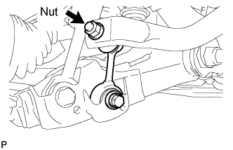
Temporarily install the stabilizer link with the bolt.
-
Temporarily install the stabilizer link with the nut.
-
Tighten the nut.
- Torque:
- 128 N*m { 1305 kgf*cm, 94 ft.*lbf }
-
-
TIGHTEN FRONT NO. 1 STABILIZER BRACKET LH
-
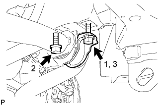
Tighten the 2 bolts of the front stabilizer brackets.
- Torque:
- 87 N*m { 887 kgf*cm, 64 ft.*lbf }
Note
Tighten the bolts in 3 steps, in the order shown in the illustration.
-
-
TIGHTEN FRONT NO. 1 STABILIZER BRACKET RH
-
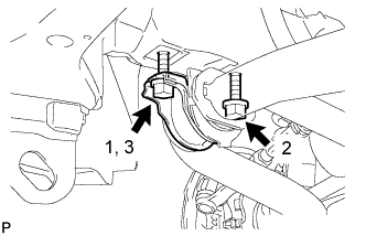
Tighten the 2 bolts of the front stabilizer brackets.
- Torque:
- 87 N*m { 887 kgf*cm, 64 ft.*lbf }
Note
Tighten the bolts in 3 steps, in the order shown in the illustration.
-
-
INSTALL NO. 1 ENGINE UNDER COVER SUB-ASSEMBLY
-
Install the No. 1 engine under cover sub-assembly with the 10 bolts.
- Torque:
- 29 N*m { 296 kgf*cm, 21 ft.*lbf }
-
-
INSTALL FRONT FENDER SPLASH SHIELD SUB-ASSEMBLY LH
-
Push in the clip to install the front fender splash shield sub-assembly LH.
-
Install the 3 bolts and 2 screws.
-
-
INSTALL FRONT FENDER SPLASH SHIELD SUB-ASSEMBLY RH
Tech Tips
Use the same procedure described for the LH side.
-
STABILIZE SUSPENSION
-
Install the front wheels.
- Torque:
- 131 N*m { 1336 kgf*cm, 97 ft.*lbf }
-
Lower the vehicle.
-
Press down on the vehicle several times to stabilize the suspension.
-
-
TIGHTEN FRONT NO. 1 SUSPENSION ARM LOWER SUB-ASSEMBLY LH
-
Tighten the bolt and nut.
- Torque:
- 280 N*m { 2855 kgf*cm, 207 ft.*lbf }
Note
Perform this procedure with all 4 wheels on the ground.
-
-
TIGHTEN FRONT SHOCK ABSORBER WITH COIL SPRING
-
Tighten the nut.
- Torque:
- 180 N*m { 1835 kgf*cm, 133 ft.*lbf }
Note
Perform this procedure with all 4 wheels on the ground.
-
-
TIGHTEN FRONT STABILIZER LINK ASSEMBLY LH
-
Tighten the bolt.
- Torque:
- 135 N*m { 1377 kgf*cm, 100 ft.*lbf }
Note
Perform this procedure with all 4 wheels on the ground.
-
-
TIGHTEN FRONT STABILIZER LINK ASSEMBLY RH
-
Tighten the bolt.
- Torque:
- 135 N*m { 1377 kgf*cm, 100 ft.*lbf }
Note
Perform this procedure with all 4 wheels on the ground.
-
-
INSPECT AND ADJUST FRONT WHEEL ALIGNMENT
-
Inspect and adjust the front wheel alignment Click here.
-
-
ADJUST HEADLIGHT ASSEMBLY
-
Adjust the headlight assembly Click here.
-