- Click here
INSTALL FRONT CRANKSHAFT OIL SEAL
-
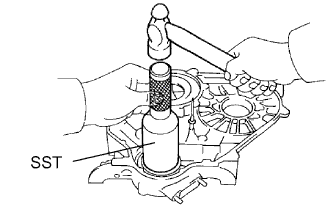
Using SST and a hammer, tap in a new oil seal until its surface is flush with the timing belt case edge.
09214-60010 -
Apply MP grease to the lip of the oil seal.
-
- Click here
INSTALL TIMING BELT CASE SUB-ASSEMBLY
-
Place a new gasket on the cylinder block.
-
Install the timing belt case with the 5 bolts.
23 N*m 230 kgf*cm 17 in.*lbf
-
- Click here
INSTALL OIL STRAINER SUB-ASSEMBLY
-
Install a new gasket and the oil strainer with the 2 bolts and 2 nuts.
for nut 21 N*m 210 kgf*cm 17 in.*lbf for bolt 18 N*m 184 kgf*cm 13 in.*lbf
-
- Click here
INSTALL OIL PAN SUB-ASSEMBLY
-
Remove any old packing (FIPG) material and do not drop any oil on the contact surfaces of the oil pan and cylinder block.
-
Using a gasket scraper, remove all the old packing (FIPG) material from the installation surface.
-
Thoroughly clean all components to remove all the loose material.
-
Using a non-residue solvent, clean both of the sealing surfaces.
Note:Do not use a solvent which will affect the painted surfaces.
-
-
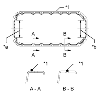
Apply seal packing to the oil pan as shown in the illustration.
Seal packing Toyota Genuine Seal Packing Black, Three Bond 1207B or equivalent Application Specification Item Seal Packing Diameter Seal Packing Application Length Dashed line 7.0 mm (0.276 in.) 128 mm (5.04 in.) Continuous line 5.0 mm (0.197 in.) - Table 1. Text in Illustration *1 Seal Packing *a Timing Belt Case Contact Portion *b Rear Oil Seal Retainer Contact Portion Tip:
-
Do not apply an excessive amount to the surface, especially near the oil passages.
-
Parts must be assembled within 5 minutes of application. Otherwise the material must be removed and reapplied.
-
-
Install the oil pan with the 16 bolts and 2 nuts. Uniformly tighten the bolts and nuts in several steps.
18 N*m 184 kgf*cm 13 in.*lbf
-
- Click here
INSTALL CRANKSHAFT TIMING PULLEY
-
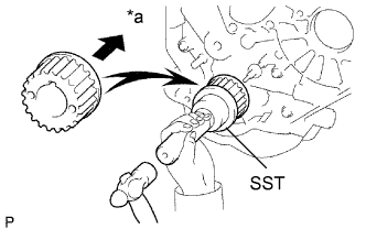
Align the key groove of the timing pulley with the pulley set key.
-
Using SST and a hammer, tap in the timing pulley with the flange side facing inward.
09223-46011 Table 2. Text in Illustration *a Inside
-
- Click here
INSTALL NO. 2 TIMING BELT IDLER SUB-ASSEMBLY
-
Install the spacer and No. 2 timing belt idler with the bolt.
33 N*m 337 kgf*cm 24 in.*lbf -
Check that the No. 2 timing belt idler moves smoothly.
-
- Click here
INSTALL NO. 1 TIMING BELT IDLER SUB-ASSEMBLY
-
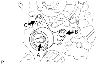
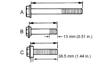
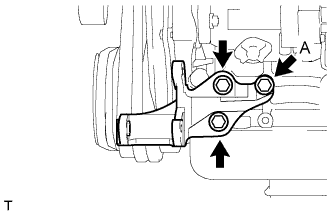
Install the No. 1 belt idler with the 3 bolts.
for bolt A 44 N*m 449 kgf*cm 32 in.*lbf for bolt B, C 19 N*m 195 kgf*cm 14 in.*lbf Tip:
-
-
The bolt lengths for bolt A, B and C as follows.
-
Bolt C is combined with the No. 1 timing belt idler.
Standard Bolt Item Length A 76.5 mm (3.01 in.) B 42.9 mm (1.69 in.) C 41.3 mm (1.63 in.) -
-
- Click here
INSTALL WATER PUMP ASSEMBLY
-
Install a new gasket, the water pump and tension spring bracket with the 6 bolts.
23 N*m 236 kgf*cm 17 in.*lbf
-
- Click here
INSTALL NO. 2 TIMING BELT COVER
-
Install the timing belt cover with the 4 bolts.
18 N*m 184 kgf*cm 13 in.*lbf
-
- Click here
INSTALL CAMSHAFT TIMING PULLEY
-
Install the woodruff key to the key groove of the camshaft.
-
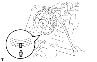
Align the timing mark on the camshaft timing pulley with the timing mark on the No. 2 timing belt cover and temporarily install the pulley with the bolt.
-
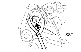
Using SST, tighten the bolt.
09960-10010 09962-01000 09963-01000 98 N*m 999 kgf*cm 72 in.*lbf
-
- Click here
INSTALL NO. 1 GENERATOR BRACKET
-
Install the generator bracket with the 3 bolts.
49 N*m 500 kgf*cm 36 in.*lbf
-
- Click here
INSTALL NO. 1 FRONT ENGINE MOUNTING BRACKET RH
-
Install the engine mounting bracket with the 4 bolts.
49 N*m 500 kgf*cm 36 in.*lbf
-
- Click here
INSTALL NO. 1 FRONT ENGINE MOUNTING BRACKET LH
-
Install the engine mounting bracket with the 4 bolts.
49 N*m 500 kgf*cm 36 in.*lbf
-
- Click here
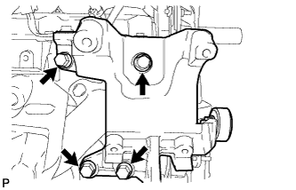
INSTALL PUMP BRACKET
-
Install the pump bracket with the 3 bolts.
for bolt A 57 N*m 581 kgf*cm 42 in.*lbf except bolt A 78 N*m 795 kgf*cm 58 in.*lbf
-
- Click here
INSTALL WATER BY-PASS HOSE UNION
-
Clean the threads of the water by-pass hose union and apply adhesive to them.
Adhesive Toyota Genuine Adhesive 1324, Three Bond 1324 or equivalent -
Install the water by-pass hose union.
39 N*m 398 kgf*cm 29 in.*lbf
-
- Click here
INSTALL WATER OUTLET HOUSING
-
Install a new gasket to the cylinder head.
-
Install the outlet hosing with the 3 bolts
19 N*m 194 kgf*cm 14 in.*lbf
-
- Click here
INSTALL INJECTION PUMP ASSEMBLY
-
Install the injection pump (Click here).
-
- Click here
INSTALL TIMING BELT
-
Install the timing belt (Click here).
-
- Click here
INSTALL NO. 1 COMPRESSOR MOUNTING BRACKET
-
Install the No. 1 compressor mounting bracket with the 4 bolts.
81 N*m 829 kgf*cm 60 in.*lbf
-
- Click here
INSTALL ENGINE ASSEMBLY
-
Install the engine (Click here).
-