БЛОК ДВИГАТЕЛЯ СНЯТИЕ

-
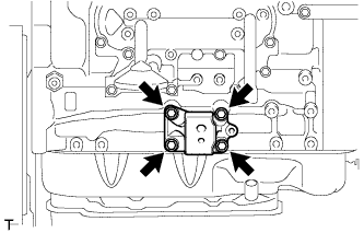
REMOVE NO. 1 COMPRESSOR MOUNTING BRACKET
-
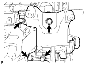
Remove the 4 bolts and compressor mounting bracket.
-
-
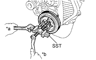
REMOVE CRANKSHAFT PULLEY

Text in Illustration *a Hold *b Turn
-
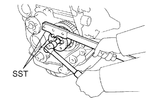
Using SST, remove the pulley bolt.
- SST
- 09213-54015 ( 91651-60855 )
- 09330-00021
-
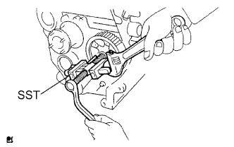
Text in Illustration *a Hold *b Turn Using SST, remove the pulley.
- SST
- 09950-50013 ( 09951-05010, 09952-05010, 09953-05020, 09954-05021 )
- 09950-60010 ( 09951-00490 )
- 09950-40011 ( 09957-04010 )
-
-
REMOVE TIMING BELT COVER
-
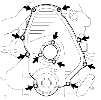
Remove the 11 bolts, washers, timing belt cover, and 2 gaskets.
-
-
SET NO. 1 CYLINDER TO TDC/COMPRESSION
-
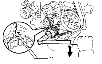
Text in Illustration *1 Timing Mark 
Turn Using the crankshaft pulley bolt, align the groove of the crankshaft pulley with the timing pointer by turning the crankshaft clockwise.
-
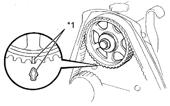
Text in Illustration *1 Timing Mark Check that the timing marks of the camshaft timing pulley and No. 2 timing belt cover are aligned.
If not, turn the crankshaft 1 revolution (360°).
-
-
REMOVE TIMING BELT
Tech Tips
If reusing the timing belt, draw a direction arrow on the timing belt (in the direction the belt move when the engine is running), and place matchmarks on the pulleys and timing belt.
-
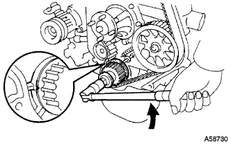
Turn the crankshaft 90° counterclockwise, and align the timing mark of the crankshaft timing pulley with the protrusion of the timing belt case.
Text in Illustration Turn Note
If the timing belt is disengaged, having the crankshaft timing pulley at the wrong angle can cause the piston head and valve head to come into contact with each other when removing the camshaft timing pulley, and camshaft causing damage. Therefore, always set the crankshaft pulley is removed at the correct angle.
-
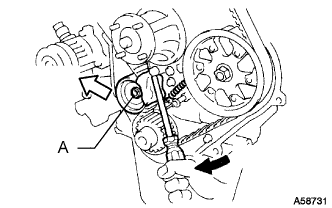
Loosen the No. 1 timing belt idler bolt (A), and shift the idler to the left as far as possible.
Text in Illustration Pry 
Move -
Tighten the No. 1 timing belt idler bolt (A), and then relieve the timing belt tension.
-
Remove the timing belt.
-
-
REMOVE CRANKSHAFT TIMING PULLEY
-
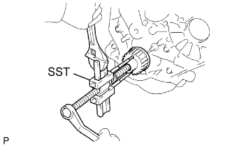
Using a screwdriver, remove the crankshaft timing pulley.
- SST
- 09950-50013 ( 09951-05010, 09952-05010, 09953-05010, 09953-05020, 09954-05010 )
Tech Tips
If the timing pulley cannot be removed by using a screwdriver, remove it with SST.
-
-
REMOVE INTAKE FLANGE
-
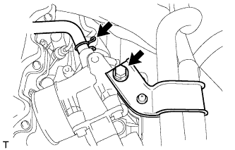
Remove the bolt and disconnect the PCV hose and heater hose bracket.
-
Disconnect the manifold absolute pressure sensor connector.
-
Remove the 3 nuts, intake flange and gasket.
-
-
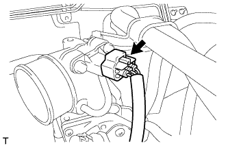
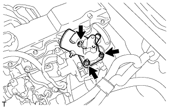
REMOVE DIESEL THROTTLE BODY
-
Disconnect the throttle open switch connector.
-
Remove the 2 bolts and disconnect the wire harness bracket.
-
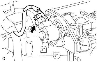
Disconnect the throttle control motor connector.
-
Remove the diesel throttle body and gasket.
-
-
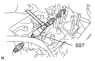
REMOVE INJECTION PIPE SET
-
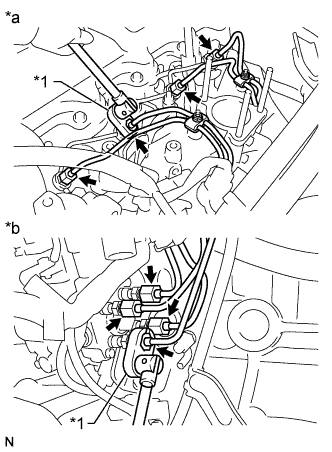
Text in Illustration *1 Union Nut Wrench *a for Injection Nozzle Side *b for Injection Pump Side Using a union nut wrench, loosen the 8 union nuts of the 4 injection pipes.
-
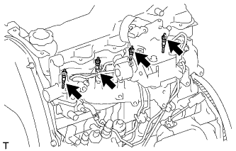
Remove the 2 nuts, 2 upper pipe clamps and 4 injection pipes with 2 lower pipe clamps.
-
-
REMOVE NO. 1 GLOW PLUG CONNECTOR
-
Remove the nut, No. 2 glow plug resistor insulator and washer and disconnect the wire harness.
-
Remove the 4 screw grommets and 4 nuts.
-
Remove the No. 1 glow plug connector and No. 1 glow plug resistor insulator.
-
-
REMOVE NOZZLE LEAKAGE PIPE ASSEMBLY
-
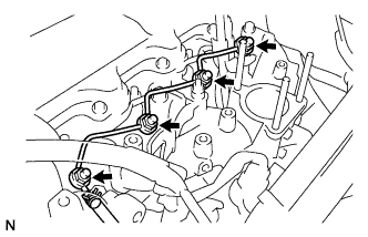
Disconnect the fuel hose from the leakage pipe.
-
Remove the 4 nuts, leakage pipe and 4 ring packing washers.
-
-
REMOVE NOZZLE HOLDER & NOZZLE SET
-
Using SST, remove the 4 injection nozzles, 4 injection nozzle seats and 4 injection nozzle seat gaskets.
- SST
- 09268-64010 ( 09268-64020 )
-
-
REMOVE GLOW PLUG ASSEMBLY
-
Using a 12 mm deep socket wrench, remove the 4 glow plugs.
-
-
REMOVE INJECTION PUMP DRIVE PULLEY
-
Using SST, remove the pulley nut.
- SST
- 09213-14010 ( 91651-60865 )
- 09330-00021
-
Using SST, remove the drive pulley.
- SST
- 09950-50013 ( 09951-05010, 09952-05010, 09953-05010, 09954-05021 )
-
-
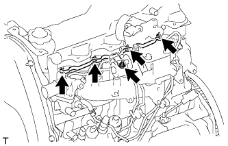
REMOVE INJECTION PUMP ASSEMBLY
-
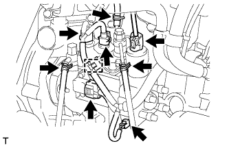
Disconnect the 5 connectors and detach the wire harness clamp.
-
Disconnect the 3 fuel hoses.
-
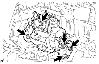
Remove the 3 bolts and injection pump stay.
-
Remove the 2 nuts and injection pump.
-
-
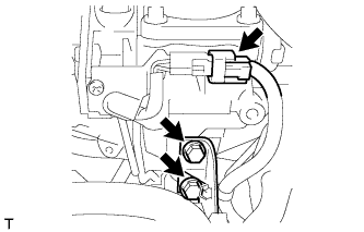
REMOVE CRANK POSITION SENSOR
-
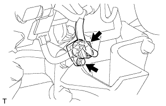
Disconnect the crankshaft position sensor connector.
-
Remove the bolt and crankshaft position sensor.
-
-
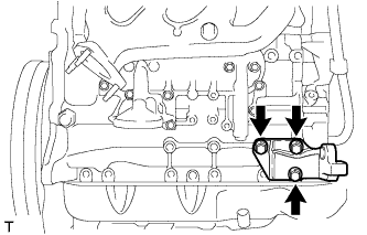
REMOVE WATER OUTLET HOUSING
-
Remove the 3 bolts, outlet housing and gasket.
-
-
REMOVE INTAKE MANIFOLD
-
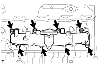
Remove the 6 bolts, 2 nuts, intake manifold and gasket.
-
-
REMOVE WATER BY-PASS HOSE UNION
-
Remove the water by-pass hose union.
-
-
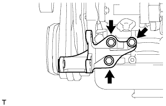
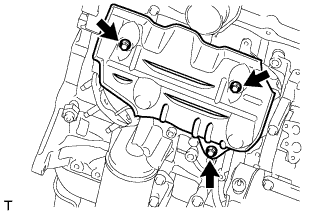
REMOVE NO. 1 GENERATOR BRACKET
-
Remove the 3 bolts and No. 1 generator bracket.
-
-
REMOVE PUMP BRACKET
-
Remove the 3 bolts and pump bracket.
-
-
REMOVE ENGINE OIL LEVEL DIPSTICK GUIDE
-
Remove the dipstick.
-
Remove the 2 bolts and dipstick guide.
-
Remove the O-ring from the dipstick guide.
-
-
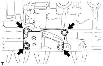
REMOVE NO. 1 FRONT ENGINE MOUNTING BRACKET RH
-
Remove the 4 bolts and engine mounting bracket.
-
-
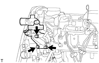
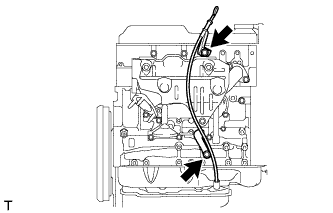
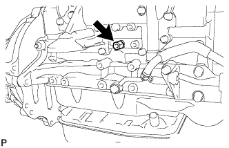
REMOVE VACUUM PUMP OIL INLET HOSE
-
Remove the union bolt and gasket, and then disconnect the vacuum pump oil inlet hose from the cylinder block.
-
-
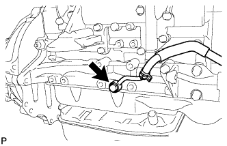
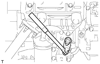
REMOVE UNION
-
Remove the union from the cylinder block.
-
-
REMOVE VACUUM PUMP OIL OUTLET HOSE
-
Remove the bolt, 2 gaskets and vacuum pump outlet hose.
-
-
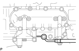
REMOVE NO. 1 FRONT ENGINE MOUNTING BRACKET LH
-
Remove the 4 bolts and engine mounting bracket.
-
-
REMOVE NO. 1 EXHAUST MANIFOLD HEAT INSULATOR
-
Remove the 3 bolts and insulator.
-
-
REMOVE EXHAUST MANIFOLD
-
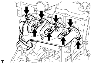
Remove the 2 nuts, 6 bolts and manifold.
-
Remove the gasket.
-
-
REMOVE OIL FILTER BRACKET SUB-ASSEMBLY
-
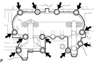
Remove the 10 bolts, 2 nuts, oil filter bracket and gasket.
-
-
REMOVE ENGINE OIL PRESSURE SWITCH ASSEMBLY
-
Using a 24 mm deep socket wrench, remove the oil pressure switch.
-