ДВИГАТЕЛЬ В СБОРЕ УСТАНОВКА

-
INSTALL FRONT ENGINE MOUNTING INSULATOR
-
Install the 2 front engine mounting insulators with the 2 nuts.
- Torque:
- 46 N*m { 469 kgf*cm, 34 ft.*lbf }
-
-
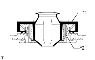
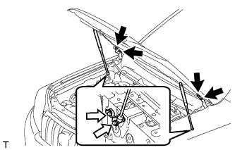
INSTALL ENGINE HANGER
-
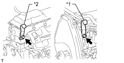
Text in Illustration *1 No. 1 Engine Hanger *2 No. 2 Engine Hanger Install an engine hanger to each location shown in the illustration.
Tech Tips
No. 1 Engine Hanger 12281-54080 No. 2 Engine Hanger 12282-54070 Bolt (No. 1 Engine Hanger) 90119-10736 Bolt (No. 2 Engine Hanger) 91622-61022 - Torque:
- for No. 1 Engine Hanger
- 59 N*m { 602 kgf*cm, 44 ft.*lbf }
- for No. 2 Engine Hanger
- 37 N*m { 377 kgf*cm, 27 ft.*lbf }
Note
Install the engine hangers with new bolts.
-
-
REMOVE ENGINE FROM ENGINE STAND
-
Attach an engine sling device and hang the engine with a chain block.
-
Lift the engine and remove it from the engine stand.
-
-
INSTALL ENGINE ASSEMBLY
-
Slowly lower the engine into the engine compartment.
-
Install the engine with the 4 bolts and 4 nuts.
- Torque:
- 40 N*m { 408 kgf*cm, 30 ft.*lbf }
Tech Tips
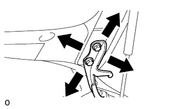
For RHD vehicles only:
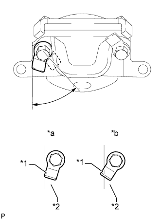
When tightening the nut closer to the rear of the vehicle for the engine mounting bracket on the right side, make sure that the claw (stopper) of the bolt does not protrude past the rear edge of the bracket.
Text in Illustration *1 Claw (Stopper) *2 Bracket *a Correct *b Incorrect -
Remove the 2 bolts and 2 engine hangers.
-
-
INSTALL FLYWHEEL HOUSING DUST SEAL
-
INSTALL REAR END PLATE
-
Install the rear end plate with the 2 bolts.
- Torque:
- 27 N*m { 275 kgf*cm, 20 ft.*lbf }
-
-
INSTALL FLYWHEEL SUB-ASSEMBLY
-
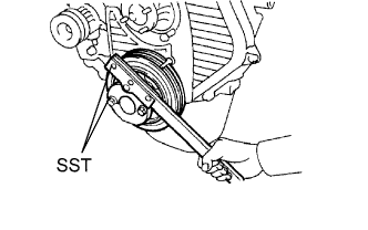
Using SST, hold the crankshaft.
- SST
- 09213-54015 ( 91651-60855 )
- 09330-00021
-
Clean the bolts and bolt holes.
-
Apply adhesive to 2 or 3 threads of each of the bolts.
Adhesive Toyota Genuine Adhesive 1324, Three Bond 1324 or equivalent -
Install the flywheel to the crankshaft.
-
Temporarily install the flywheel with the 8 bolts.
-
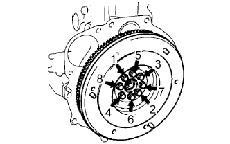
Tighten the 8 bolts uniformly in several steps in the order shown in the illustration.
- Torque:
- 123 N*m { 1249 kgf*cm, 90 ft.*lbf }
Note
Do not start the engine for at least 1 hour after installing.
-
-
INSTALL CLUTCH DISC ASSEMBLY
-
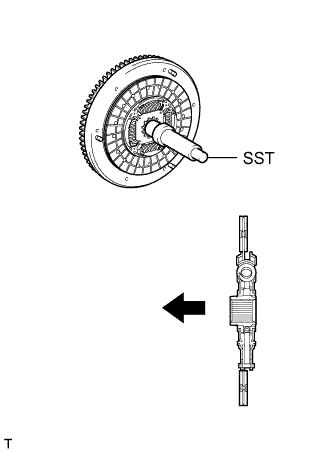
Insert SST into the clutch disc. Then insert SST (together with the clutch disc) into the flywheel to install the clutch disc.
- SST
- 09301-00110
Text in Illustration 
Flywheel Side Note
Be sure to install the clutch disc so that it is facing in the correct direction.
-
-
INSTALL CLUTCH COVER ASSEMBLY
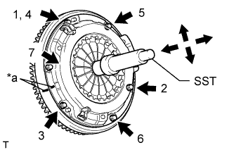
Text in Illustration *a Matchmark
-
Align the matchmarks on the clutch cover and flywheel.
-
Tighten the 6 bolts uniformly in the order shown in the illustration, starting with the bolt located near the knock pin on the top.
- SST
- 09301-00110
- Torque:
- 19 N*m { 194 kgf*cm, 14 ft.*lbf }
Tech Tips
Move SST up and down, and right and left lightly after checking that the clutch disc assembly is in the center, and then tighten the bolts.
-
-
INSTALL REAR NO. 1 ENGINE MOUNTING INSULATOR
-
Install the rear engine mounting insulator to the transmission with the 4 bolts.
Note
Perform this procedure when replacement of the engine mounting insulator is necessary.
- Torque:
- 65 N*m { 663 kgf*cm, 48 ft.*lbf }
-
-
INSTALL MANUAL TRANSMISSION ASSEMBLY
-
Install the manual transmission Click here.
-
-
INSTALL PROPELLER SHAFT ASSEMBLY
-
Совместите метки на фланце карданного вала и фланце дифференциала.
-
Установите карданный вал в сборе и закрепите его 4 болтами, 4 шайбами и 4 гайками.
- Torque:
- 88 Н*м { 899 кгс*см, 65 фунт-сила-дюймов }
-
Нанесите метки на фланец карданного вала и фланец раздаточной коробки.
-
Закрепите карданный вал в сборе с помощью 4 шайб и 4 гаек.
- Torque:
- 88 Н*м { 899 кгс*см, 65 фунт-сила-дюймов }
-
-
INSTALL FRONT PROPELLER SHAFT ASSEMBLY
-
Совместите метки на вилке и фланце дифференциала.
-
Установите карданный вал в сборе и закрепите его 4 болтами, 4 шайбами и 4 гайками.
- Torque:
- 88 Н*м { 899 кгс*см, 65 фунт-сила-дюймов }
-
Совместите метки на вилке и фланце раздаточной коробки.
-
Закрепите карданный вал в сборе с помощью 4 шайб и 4 гаек.
- Torque:
- 88 Н*м { 899 кгс*см, 65 фунт-сила-дюймов }
-
-
INSTALL FRONT EXHAUST PIPE ASSEMBLY
-
Install a new gasket and the front exhaust pipe to the exhaust manifold with 3 new nuts.
- Torque:
- 54 N*m { 554 kgf*cm, 40 ft.*lbf }
-
Install the No. 1 exhaust pipe support bracket with the 2 bolts.
- Torque:
- 71 N*m { 724 kgf*cm, 52 ft.*lbf }
-
Install the clamp with the bolt.
- Torque:
- 19 N*m { 194 kgf*cm, 14 ft.*lbf }
-
-
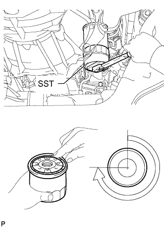
INSTALL OIL FILTER SUB-ASSEMBLY
-
Check and clean the oil filter installation surface.
-
Apply clean engine oil to the gasket of a new oil filter.
-
Install the oil filter and tighten it by hand until the gasket contacts the installation surface.
-
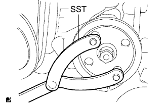
Using SST, tighten the oil filter. Choose from the following to further tighten the oil filter.
- SST
- 09228-44011
-
Using a torque wrench, tighten the oil filter.
- Torque:
- 17 N*m { 173 kgf*cm, 13 ft.*lbf }
-
Tighten the oil filter a 3/4 turn by hand or with a common wrench.
Text in Illustration 
3/4 turn
-
-
INSTALL STARTER ASSEMBLY
-
Install the starter with the 2 bolts and nut.
- Torque:
- 68 N*m { 693 kgf*cm, 50 ft.*lbf }
-
Connect the starter wire with the nut.
- Torque:
- 9.8 N*m { 100 kgf*cm, 87 in.*lbf }
-
Install the terminal cap.
-
Connect the starter connector.
-
-
CONNECT CLUTCH RELEASE CYLINDER ASSEMBLY
-
Подсоедините рабочий цилиндр с помощью 2 болтов.
- Torque:
- 12 Н*м { 120 кгс*см, 9 фунт-сила-дюймов }
-
-
INSTALL VANE PUMP ASSEMBLY
-
Temporarily install the vane pump with the 2 bolts and nut.
-
Install the pulley to the pump shaft.
-
Using SST, hold the pulley and install the nut.
- SST
- 09960-10010 ( 09962-01000, 09963-01000 )
- Torque:
- 43 N*m { 443 kgf*cm, 31 ft.*lbf }
-
-
CONNECT FUEL HOSE
-
Connect the 2 fuel hoses.
-
-
CONNECT HEATER WATER HOSE ASSEMBLY
-
Connect the 2 water hoses.
-
Install the heater water hose clamp with the bolt.
- Torque:
- 14 N*m { 138 kgf*cm, 10 ft.*lbf }
-
-
INSTALL WIRING HARNESS CLAMP BRACKET (for LHD)
-
Install the wiring harness clamp bracket with the bolt.
- Torque:
- 22 N*m { 219 kgf*cm, 16 ft.*lbf }
-
-
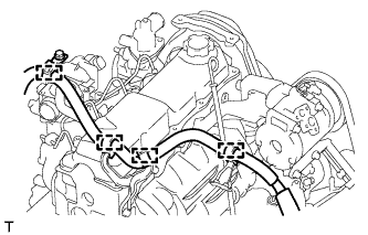
CONNECT ENGINE WIRE
-
Connect the ECM connector.
-
Text in Illustration *1 Grommet *2 Wire Harness Support Attach the grommet to the wire harness support.
-
Pass the wire harness into the vehicle and install the wire harness support.
-
-
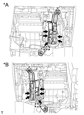
Text in Illustration *A for LHD *B for RHD Connect the 5 ECM connectors and attach the clamp.
-
for LHD:
Connect the 4 wire harness clamps.
-
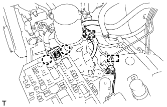
Attach the 2 clamps and connect the connector.
-
Attach the 2 claws and install the nut.
- Torque:
- 11 N*m { 112 kgf*cm, 8 ft.*lbf }
-
Install the No. 1 relay block cover.
-
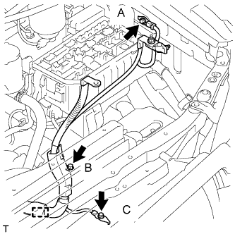
Attach the clamp and install the 3 bolts.
- Torque:
- for bolt A
- 8.5 N*m { 87 kgf*cm, 75 in.*lbf }
- for bolt B
- 8.0 N*m { 82 kgf*cm, 71 in.*lbf }
- for bolt C
- 19 N*m { 194 kgf*cm, 14 ft.*lbf }
-
-
INSTALL GLOVE COMPARTMENT DOOR ASSEMBLY
-
Install the glove compartment door Click here.
-
-
INSTALL GENERATOR ASSEMBLY
-
Temporarily install the generator with the 2 bolts.
-
Connect the vacuum pump oil outlet hose.
-
Install 2 new gaskets and the vacuum pump oil inlet hose with the union bolt.
- Torque:
- 14 N*m { 140 kgf*cm, 10 ft.*lbf }
-
Connect the vacuum pump hose.
-
Attach the vacuum pump oil inlet hose to the cord clip.
-
Install the generator wire with the nut.
- Torque:
- 9.8 N*m { 100 kgf*cm, 87 in.*lbf }
-
Install the terminal cap.
-
Connect the generator connector.
-
-
CONNECT COOLER COMPRESSOR ASSEMBLY
-
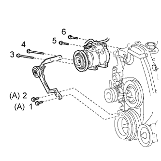
Temporarily install the cooler compressor with the 2 bolts.
-
Temporarily install the idle pulley bracket with the 4 bolts.
-
Tighten the 6 bolts in the sequence shown in the illustration.
- Torque:
- for bolt A
- 45 N*m { 459 kgf*cm, 33 ft.*lbf }
- except bolt A
- 25 N*m { 250 kgf*cm, 18 ft.*lbf }
-
Connect the wire harness with the bolt.
- Torque:
- 13 N*m { 131 kgf*cm, 9 ft.*lbf }
-
Connect the cooler compressor connector.
-
-
INSTALL INTAKE PIPE ASSEMBLY
-
Install the intake pipe with the 2 bolts.
- Torque:
- 18 N*m { 184 kgf*cm, 13 ft.*lbf }
-
Tighten the intake pipe clamp.
- Torque:
- 6.0 N*m { 61 kgf*cm, 53 in.*lbf }
-
-
INSTALL RADIATOR ASSEMBLY
-
Insert the tabs of the radiator support into the radiator service holes.
-
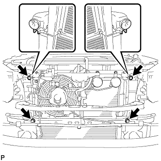
Install the radiator with the 4 bolts.
- Torque:
- 18 N*m { 184 kgf*cm, 13 ft.*lbf }
-
-
INSTALL FAN SHROUD
-
Install the fan pulley to the water pump.
-
Install the shroud together with the coupling fan between the radiator and engine.
Note
Be careful not to damage the radiator core.
-
Temporarily install the fluid coupling fan to the fan pulley with the 4 nuts. Tighten the nuts as much as possible by hand.
-
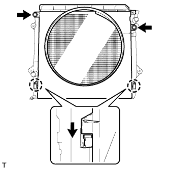
Attach the claws of the shroud as shown in the illustration.
-
Install the shroud with the 2 bolts.
- Torque:
- 5.0 N*m { 51 kgf*cm, 44 in.*lbf }
-
Install the fan and generator V belt and vane pump V belt Click here.
-
Tighten the 4 nuts of the fluid coupling fan.
- Torque:
- 19 N*m { 189 kgf*cm, 14 ft.*lbf }
-
-
INSTALL NO. 2 RADIATOR HOSE
-
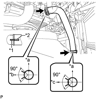
Text in Illustration *a Upper *b Front Side of Vehicle *c LH Side *1 Protrusion *2 Paint Mark Install the radiator hose.
Tech Tips
Position the hose clamps as shown in the illustration.
-
-
INSTALL NO. 1 RADIATOR HOSE
-
Install the hose clamp with the 2 nuts.
- Torque:
- 8.5 N*m { 87 kgf*cm, 75 in.*lbf }
-
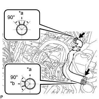
Text in Illustration *a Upper *b RH Side Install the radiator hose.
Tech Tips
Position the hose clamps as shown in the illustration.
-
-
INSTALL RADIATOR SIDE DEFLECTOR RH
-
Attach the 3 claws.
-
Install the deflector with the clip.
-
-
INSTALL RADIATOR SIDE DEFLECTOR LH
-
Attach the 3 claws.
-
Install the deflector with the clip.
-
-
INSTALL UPPER FRONT BUMPER RETAINER
-
Install the upper retainer with the 3 bolts.
- Torque:
- 8.0 N*m { 82 kgf*cm, 71 in.*lbf }
-
-
INSTALL FRONT BUMPER COVER
-
Для моделей с сенсорной системой помощи при парковке TOYOTA и противотуманными фарами:
Подсоедините 3 разъема.
-
Для моделей с сенсорной системой помощи при парковке TOYOTA без противотуманных фар:
Подсоедините 2 разъема.
-
Для моделей без сенсорной системы помощи при парковке TOYOTA и с противотуманными фарами:
Подсоедините разъем.
-
Для моделей с системой очистителей фар:
Подсоедините шланг очистителя фар.
-
Закрепите 12 захватов, чтобы установить накладку переднего бампера.
-
Вверните 2 болта A, 2 болта B, 6 винтов и 6 фиксаторов.
- Torque:
- Болт A
- 8,0 Н*м { 82 кгс*см, 71 фунт-сила-дюйм }
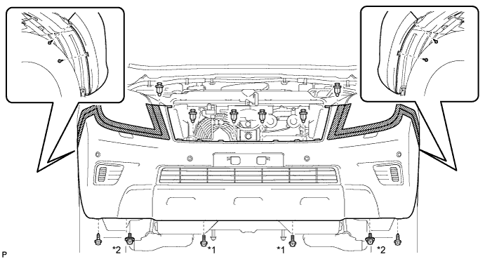
Обозначения на рисунке *1 Болт A *2 Болт B
-
-
INSTALL AIR CLEANER CASE ASSEMBLY
-
Install the air cleaner case with the 3 bolts.
- Torque:
- 12 N*m { 122 kgf*cm, 9 ft.*lbf }
-
-
INSTALL AIR CLEANER FILTER ELEMENT SUB-ASSEMBLY
-
INSTALL RESONATOR WITH AIR CLEANER CAP SUB-ASSEMBLY
-
Вставьте петли крышки воздушного фильтра и шланг в корпус воздушного фильтра, а затем закрепите 4 откидных защелки.
-
Установите крышку воздушного фильтра и закрепите ее зажимом.
- Torque:
- 5,0 Н*м { 51 кгс*см, 44 фунт-сила-дюйма }
-
Закрепите зажим жгута проводов.
-
Подсоедините 2 зажима и разъем.
-
-
INSTALL NO. 1 FRONT FENDER APRON TO FRAME SEAL LH
-
Install the No. 1 front fender apron to frame seal with the 5 clips.
-
-
INSTALL FRONT FENDER APRON SEAL LH
-
Install the front fender apron seal with the 5 clips.
-
-
INSTALL NO. 1 FRONT FENDER APRON TO FRAME SEAL RH
-
Install the No. 1 front fender apron to frame seal with the 5 clips.
-
-
INSTALL FRONT FENDER APRON SEAL RH
-
Install the front fender apron seal with the 4 clips.
-
-
INSTALL REAR ENGINE UNDER COVER ASSEMBLY
-
Install the rear engine under cover with the 4 bolts.
- Torque:
- 29 N*m { 296 kgf*cm, 21 ft.*lbf }
-
-
INSTALL TRANSMISSION UNDER COVER
-
Install the transmission under cover with the 2 bolts.
- Torque:
- 29 N*m { 296 kgf*cm, 21 ft.*lbf }
-
-
INSTALL NO. 1 ENGINE UNDER COVER SUB-ASSEMBLY
-
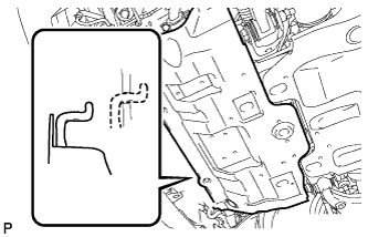
Hook the engine under cover to the vehicle body as shown in the illustration.
-
Install the 4 bolts.
- Torque:
- 29 N*m { 296 kgf*cm, 21 ft.*lbf }
-
-
INSTALL FRONT BUMPER COVER LOWER
-
Install the front bumper cover lower with the 5 bolts and clip.
- Torque:
- 8.0 N*m { 82 kgf*cm, 71 in.*lbf }
-
-
INSTALL UPPER RADIATOR SUPPORT SEAL
-
Установите верхнее уплотнение кронштейна радиатора и закрепите его 13 фиксаторами.
-
-
INSTALL COWL TOP VENTILATOR LOUVER SUB-ASSEMBLY
-
Install the cowl top ventilator louver Click here.
-
-
INSTALL HOOD SUB-ASSEMBLY
-
Install the hood with the 8 bolts.
- Torque:
- for bolt A
- 13 N*m { 133 kgf*cm, 10 ft.*lbf }
- for bolt B
- 18 N*m { 184 kgf*cm, 13 ft.*lbf }
Text in Illustration 
Bolt A 
Bolt B -
Connect the washer nozzle hose.
-
-
ADJUST HOOD SUB-ASSEMBLY
-
Отрегулируйте положение капота.
-
Ослабьте 4 болта петель капота.
-
Для регулировки зазора между капотом и передним крылом подвиньте капот.
-
Затяните 4 болта петель капота.
- Torque:
- 13 Н*м { 133 кгс*см, 10 фунт-сила-дюймов }
-
-
Отрегулируйте высоту передней части капота с помощью резиновых амортизаторов.
-
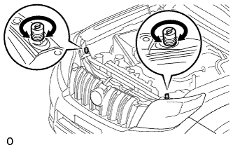
Отрегулируйте 2 резиновых амортизатора таким образом, чтобы капот и крыло оказались на одном уровне.
Tech Tips
Отрегулируйте высоту передней части капота, поворачивая 2 резиновых амортизатора.
-
-
Отрегулируйте замок капота.
-
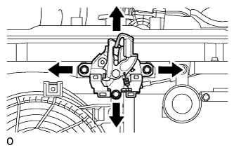
Ослабьте 3 болта.
-
Отрегулируйте замок капота и затяните 3 болта.
- Torque:
- 7,5 Н*м { 76 кгс*см, 66 фунт-сила-дюймов }
-
Убедитесь, что защелка плавно входит в зацепление с замком капота.
-
-
-
INSTALL BATTERY TRAY
-
INSTALL BATTERY
-
INSTALL BATTERY HOLD DOWN CLAMP
-
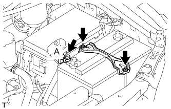
Install the battery hold down clamp with the 2 nuts.
- Torque:
- 6.0 N*m { 61 kgf*cm, 53 in.*lbf }
-
Connect the engine wire with the nut labeled A.
- Torque:
- 7.5 N*m { 76 kgf*cm, 66 in.*lbf }
-
-
CONNECT CABLE TO NEGATIVE BATTERY TERMINAL
Note
When disconnecting the cable, some systems need to be initialized after the cable is reconnected Click here.
-
ADD ENGINE OIL
-
Add fresh engine oil.
Standard Engine Oil Oil Grade Oil Viscosity (SAE) API CF-4 or CF 10W-30 Standard Capacity Item Specified Condition Drain and refill without oil filter change 6.0 liters (6.3 US qts, 5.3 Imp. qts) Drain and refill with oil filter change 6.9 liters (7.3 US qts, 6.1 Imp. qts) Dry fill 7.6 liters (8.0 US qts, 6.7 Imp. qts) -
Install the oil filler cap.
-
-
ADD ENGINE COOLANT
-
Затяните пробку сливного крана радиатора вручную.
-
Затяните пробку сливного крана блока цилиндров.
- Torque:
- 13 Н*м { 130 кгс*см, 9 фунт-сила-дюймов }
-
Медленно заполните систему охлаждающей жидкостью двигателя.
Номинальный объем 8,6 литра (9,0 кварты США, 7,6 английской кварты) Note
Не доливайте простую воду вместо охлаждающей жидкости двигателя.
Tech Tips
-
Разрешается использовать только охлаждающую жидкость "Toyota Super Long Life Coolant" или аналогичную высококачественную охлаждающую жидкость на основе этиленгликоля (но не на силикатной, аминовой, нитритной или борнокислой основе), изготовленную по гибридной технологии органических кислот с длительным сроком годности (охлаждающая жидкость, изготовленная по гибридной технологии органических кислот, состоит из низкофосфатных соединений и органических кислот.)
-
Новые автомобили Toyota заправлены охлаждающей жидкостью "Toyota Super Long Life Coolant". Для замены рекомендуется использовать охлаждающую жидкость "Toyota Super Long Life Coolant" (розового цвета, предварительно смешанная, с концентрацией этиленгликоля около 50% и температурой замерзания -35°C (-31°F)).
-
-
Медленно залейте охлаждающую жидкость в расширительный бачок радиатора до отметки "FULL".
-
Установите пробку расширительного бачка.
-
Несколько раз сожмите рукой патрубки радиатора № 1 и № 2, а затем проверьте уровень охлаждающей жидкости. Если уровень охлаждающей жидкости недостаточен, добавьте жидкость.
-
Установите на место пробку радиатора.
-
Запустите двигатель и прогрейте его до открывания термостата.
Tech Tips
Время открывания термостата можно распознать, сжав шланг радиатора № 2 рукой и отметив момент, когда охлаждающая жидкость двигателя начнет поступать в шланг.
-
Поддерживайте частоту вращения коленчатого вала двигателя 2000–2500 об/мин.
Note
-
Убедитесь, что в расширительном бачке радиатора осталась охлаждающая жидкость.
-
Обратите внимание на стрелку датчика температуры охлаждающей жидкости. Убедитесь, что значение температуры не превышает норму.
-
В случае недостатка охлаждающей жидкости двигатель может закипеть или перегреться.
-
Если в расширительном бачке радиатора нет охлаждающей жидкости, сразу после запуска двигателя выполните следующие действия: 1) остановите двигатель, 2) подождите, пока охлаждающая жидкость остынет, и 3) долейте охлаждающую жидкость до линии "F".
-
Запустите двигатель, обеспечив частоту вращения коленчатого вала 2000 об/мин, и дайте ему поработать, пока уровень охлаждающей жидкости не стабилизируется.
-
-
Несколько раз сожмите патрубки радиатора № 1 и № 2 рукой, чтобы удалить воздух.
CAUTION:
-
Работайте в защитных перчатках. Нагретые участки деталей могут травмировать руки.
-
Будьте осторожны: патрубки радиатора горячие.
-
Не приближайте свои руки к вентилятору.
-
-
Остановите двигатель и подождите, пока охлаждающая жидкость остынет до температуры окружающего воздуха.
CAUTION:
Не снимайте пробку радиатора, пока двигатель и радиатор не остынут. Выброс горячей охлаждающей жидкости и пара под давлением может стать причиной серьезных ожогов.
-
Убедитесь, что уровень охлаждающей жидкости находится между отметками "LOW" и "FULL".
Если уровень охлаждающей жидкости ниже линии "Low", повторите все вышеперечисленные действия.
Если уровень охлаждающей жидкости выше уровня "FULL", слейте охлаждающую жидкость до уровня между отметками "FULL" и "LOW".
-
-
TIGHTEN FUEL TANK CAP ASSEMBLY
-
BLEED AIR FROM FUEL SYSTEM
-
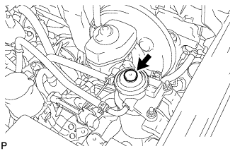
Using the hand pump mounted on the fuel filter cap, bleed the air from the fuel system. Continue pumping until the pump resistance increases.
-
-
INSPECT FOR FUEL LEAK
-
Check that there are no fuel leaks anywhere in the fuel system after performing maintenance.
Tech Tips
When checking for fuel leaks, make sure that there is pressure in the fuel line.
-
-
INSPECT FOR ENGINE OIL LEAK
-
Start the engine. Make sure that there are no oil leaks from the areas that were worked on.
-
-
INSPECT FOR COOLANT LEAK
CAUTION:
To avoid being burned, do not remove the radiator reservoir cap while the engine and radiator are still hot. Thermal expansion may cause hot engine coolant and steam to blow out from the radiator.
-
Fill the radiator with coolant and attach a radiator cap tester to the radiator.
-
Warm up the engine.
-
Using a radiator cap tester, increase the pressure inside the radiator to 123 kPa (1.3 kgf/cm2, 18 psi), and check that the pressure does not drop.
If the pressure drops, check the hoses, radiator or water pump for leaks. If no external leaks are found, check the heater core, cylinder block, and cylinder head.
-
-
ADD MANUAL TRANSMISSION OIL
-
INSPECT FOR GAS LEAK
-
If gas is leaking, tighten the areas necessary to stop the leak. Replace damaged parts as necessary.
-
-
INSPECT ENGINE IDLE SPEED
-
Warm up the engine.
-
When using the intelligent tester:
-
Connect the intelligent tester to the DLC3.
Idle speed 720 to 820 rpm Note
-
Turn all the electrical systems and the A/C off.
-
When checking the idling speed, the shift lever should be in neutral.
Tech Tips
Refer to the intelligent tester operator's manual for further details.
-
-
-
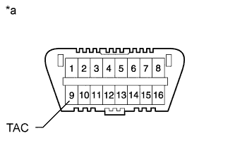
Text in Illustration *a Front View of DLC3 When not using an intelligent tester:
-
Using SST, connect the tachometer test probe to terminal 9 (TAC) of the DLC3.
- SST
- 09843-18040
-
Check the idle speed.
Standard idle speed 720 to 820 rpm Note
-
Turn all the electrical systems and the A/C off.
-
When checking the idling speed, the shift lever should be in neutral.
-
Confirm the terminal number before connecting them. Connecting the wrong terminal can be damage the engine.
-
-
-
-
INSPECT MAXIMUM ENGINE SPEED
-
Start the engine.
-
Fully depress the accelerator pedal.
-
Check the maximum speed.
Maximum engine speed 4850 to 4950 rpm
-