ДВИГАТЕЛЬ В СБОРЕ СНЯТИЕ

-
DISCONNECT CABLE FROM NEGATIVE BATTERY TERMINAL
Note
-
After turning the ignition switch off, waiting time may be required before disconnecting the cable from the battery terminal. Therefore, make sure to read the disconnecting the cable from the battery terminal notice before proceeding with work Click here.
-
When disconnecting the cable, some systems need to be initialized after the cable is reconnected Click here.
-
-
REMOVE BATTERY HOLD DOWN CLAMP
-
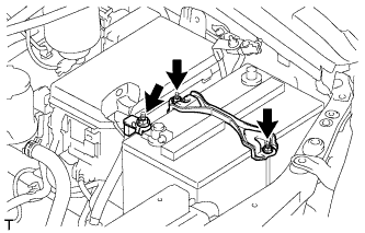
Remove the nut and disconnect the engine wire.
-
Remove the 2 nuts and battery hold down clamp.
-
-
REMOVE BATTERY
-
REMOVE BATTERY TRAY
-
REMOVE HOOD SUB-ASSEMBLY
-
Disconnect the washer nozzle hose.
-
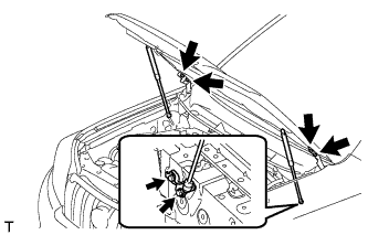
Remove the 8 bolts and hood.
Note
If the hood support is detached from the ball joint, it become non-reusable. Therefore, do not detach the hood support from the ball joint unless replacing it.
-
-
REMOVE COWL TOP VENTILATOR LOUVER SUB-ASSEMBLY
-
Remove the cowl top ventilator louver Click here.
-
-
REMOVE UPPER RADIATOR SUPPORT SEAL
-
Освободите 13 фиксаторов и снимите верхнее уплотнение кронштейна радиатора.
-
-
REMOVE FRONT BUMPER COVER LOWER
-
Remove the clip, 5 bolts and front bumper cover lower.
-
-
REMOVE NO. 1 ENGINE UNDER COVER SUB-ASSEMBLY
-
Remove the 4 bolts.
-
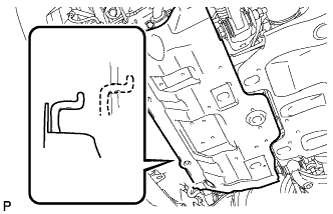
Unhook the engine under cover from the vehicle body as shown in the illustration.
-
-
REMOVE TRANSMISSION UNDER COVER
-
Remove the 2 bolts and transmission under cover.
-
-
REMOVE REAR ENGINE UNDER COVER ASSEMBLY
-
Remove the 4 bolts and rear engine under cover.
-
-
DRAIN ENGINE COOLANT
CAUTION:
Не снимайте пробку расширительного бачка радиатора, пока двигатель и радиатор не остынут. Выброс горячей охлаждающей жидкости и пара под давлением может стать причиной серьезных ожогов.
-
Ослабьте пробку сливного крана радиатора.
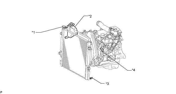
Обозначения на рисунке *1 Пробка радиатора *2 Бачок радиатора *3 Пробка сливного крана радиатора *4 Пробка сливного крана блока цилиндров Tech Tips
Слейте охлаждающую жидкость в контейнер и утилизируйте ее в соответствии с местными требованиями.
-
Слейте охлаждающую жидкость, сняв крышку радиатора.
-
Ослабьте пробку сливного крана блока цилиндров.
-
Ослабьте пробку сливного крана блока цилиндров и слейте охлаждающую жидкость из двигателя.
Note
Если охлаждающая жидкость не сливается через пробку сливного крана радиатора, пробки сливных кранов блока цилиндров и расширительный бачок радиатора, возможны засорение радиатора и утечка охлаждающей жидкости через уплотнение насоса системы охлаждения.
-
-
DRAIN ENGINE OIL
-
Remove the oil filler cap.
-
Remove the oil drain plug and gasket, and then drain the oil into a container.
-
Clean the drain plug and install it with a new gasket.
- Torque:
- 35 N*m { 352 kgf*cm, 25 ft.*lbf }
-
-
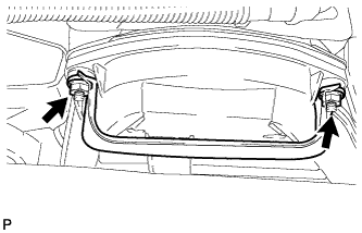
REMOVE FRONT FENDER APRON SEAL RH
-
Remove the 4 clips and fender apron seal.
-
-
REMOVE NO. 1 FRONT FENDER APRON TO FRAME SEAL RH
-
Remove the 5 clips and frame seal.
-
-
REMOVE FRONT FENDER APRON SEAL LH
-
Remove the 5 clips and fender apron seal.
-
-
REMOVE NO. 1 FRONT FENDER APRON TO FRAME SEAL LH
-
Remove the 5 clips and frame seal.
-
-
REMOVE RESONATOR WITH AIR CLEANER CAP SUB-ASSEMBLY
-
Disconnect the sensor connector.
-
Detach the wire harness clamp.
-
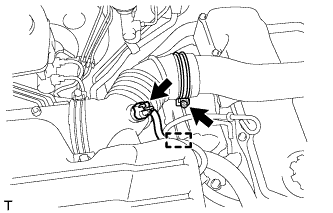
Loosen the hose clamp and remove the resonator with air cleaner cap.
-
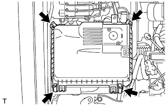
Detach the 4 hook clamps, and then remove the air cleaner cap and resonator with air cleaner cap.
-
-
REMOVE AIR CLEANER FILTER ELEMENT SUB-ASSEMBLY
-
REMOVE AIR CLEANER CASE ASSEMBLY
-
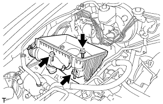
Remove the 3 bolts and air cleaner case.
-
-
REMOVE FRONT BUMPER COVER
-
Наклейте защитную ленту вокруг накладки переднего бампера.
-
Выверните 2 болта A и 2 болта B.
-
Выверните 6 винтов и освободите 6 фиксаторов.
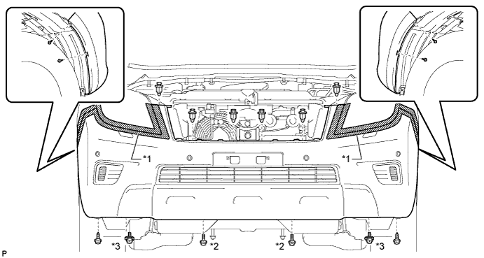
Обозначения на рисунке *1 Защитная клейкая лента *2 Болт A *3 Болт B - - -
Освободите 12 захватов.
-
Для моделей с сенсорной системой помощи при парковке TOYOTA и противотуманными фарами:
Отсоедините 3 разъема.
-
Для моделей с сенсорной системой помощи при парковке TOYOTA без противотуманных фар:
Отсоедините разъем.
-
Для моделей без сенсорной системы помощи при парковке TOYOTA и с противотуманными фарами:
Отсоедините 2 разъема.
-
Для моделей с системой очистителей фар:
Отсоедините шланг очистителя фар.
-
Снимите облицовку переднего бампера.
Обозначения на рисунке *1 Защитная клейкая лента - -
-
-
REMOVE FRONT UPPER BUMPER RETAINER
-
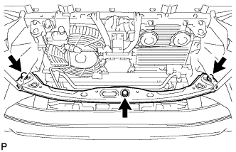
Remove the 3 bolts and retainer.
-
-
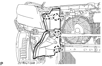
REMOVE RADIATOR SIDE DEFLECTOR LH
-
Using a clip remover, detach the 3 claws and remove the clip. Then move the side deflector so that the radiator can be removed in the step below.
-
-
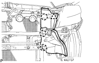
REMOVE RADIATOR SIDE DEFLECTOR RH
-
Using a clip remover, detach the 3 claws and remove the clip. Then move the side deflector so that the radiator can be removed in the step below.
-
-
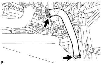
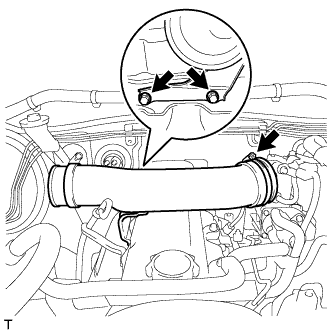
REMOVE NO. 1 RADIATOR HOSE
-
Detach the clamp and remove the No. 1 radiator hose.
-
Remove the 2 nuts and hose clamp.
-
-
REMOVE NO. 2 RADIATOR HOSE
-
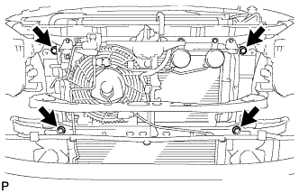
REMOVE FAN SHROUD
-
Loosen the 4 nuts holding the fluid coupling fan.
-
Remove the vane pump V belt and the fan and generator V belt Click here.
-
Remove the 2 bolts holding the fan shroud.
-
Remove the 4 nuts of the fluid coupling fan, and then remove the shroud together with the coupling fan.
Note
Be careful not to damage the radiator core.
-
Remove the fan pulley from the water pump.
-
-
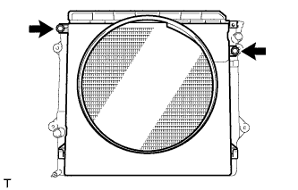
REMOVE RADIATOR ASSEMBLY
-
Remove the 4 bolts and radiator.
-
-
REMOVE INTAKE PIPE ASSEMBLY
-
Loosen the hose clamp and remove the 2 bolts and intake pipe.
-
-
DISCONNECT COOLER COMPRESSOR ASSEMBLY
-
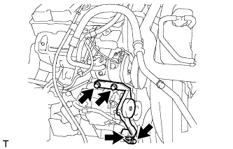
Remove the 4 bolts and idle pulley bracket.
-
Disconnect the connector.
-
Remove the 3 bolts and disconnect the cooler compressor.
Tech Tips
It is not necessary to completely remove the cooler compressor. With the hoses connected to the compressor, hang the compressor on the vehicle body with a rope.
-
-
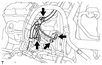
REMOVE GENERATOR ASSEMBLY
-
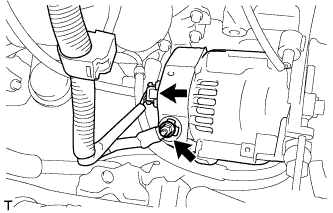
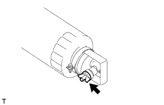
Remove the terminal cap.
-
Remove the nut and generator wire.
-
Disconnect the generator connector.
-
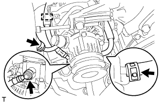
Disconnect the vacuum pump hose.
-
Remove the union bolt to disconnect the vacuum pump oil inlet hose and remove the 2 gaskets.
-
Detach the vacuum pump oil inlet hose from the cord clip.
-
Disconnect the vacuum pump oil outlet hose.
-
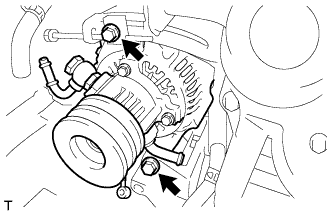
Remove the 2 bolts and generator.
-
-
REMOVE GLOVE COMPARTMENT DOOR ASSEMBLY
-
Remove the glove compartment door Click here.
-
-
DISCONNECT ENGINE WIRE
-
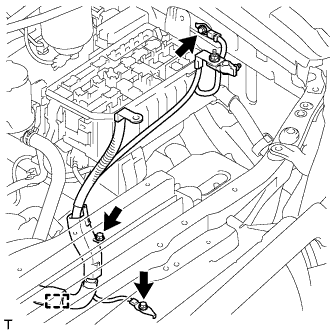
Remove the 3 bolts, detach the clamp and disconnect the engine wire.
-
Remove the No. 1 relay block cover.
-
Remove the nut and detach the 2 claws.
-
Disconnect the connector.
-
Detach the 2 clamps and disconnect the engine wire.
-
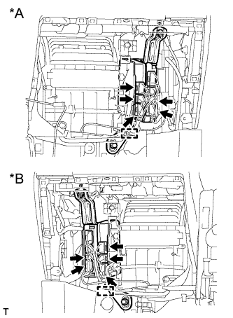
for LHD:
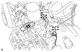
Detach the 4 clamps.
-
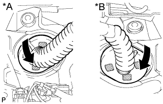
Text in Illustration *A for LHD *B for RHD Detach the grommet from the wire harness support.
-
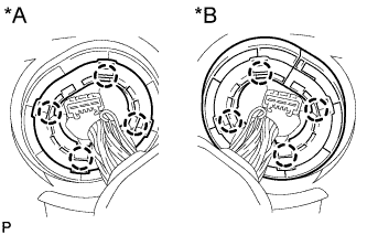
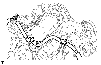
Text in Illustration *A for LHD *B for RHD Detach the 4 claws to remove the wire harness support from the vehicle, and then pull out the ECM connector to remove it from the vehicle.
-
Text in Illustration *A for LHD *B for RHD Detach the clamp and disconnect the 5 connectors as shown in the illustration.
-
-
REMOVE WIRING HARNESS CLAMP BRACKET (for LHD)
-
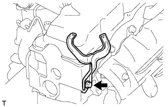
Remove the bolt and wiring harness clamp bracket.
-
-
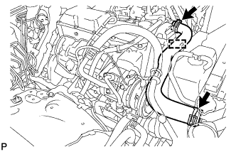
DISCONNECT HEATER WATER HOSE ASSEMBLY
-
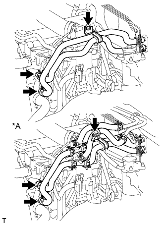
Text in Illustration *A for Rear Heater Remove the bolt and disconnect the heater water hoses.
-
-
LOOSEN FUEL TANK CAP ASSEMBLY
-
DRAIN FUEL
-
Loosen the fuel filter drain plug and drain the fuel from the fuel filter.
-
-
DISCONNECT FUEL HOSE
-
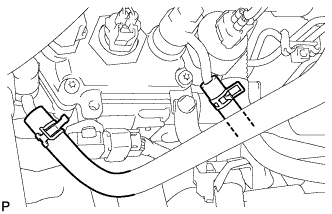
Disconnect the 2 fuel hoses.
-
-
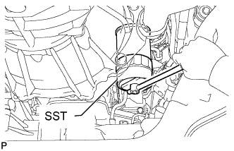
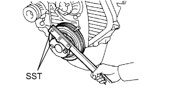
DISCONNECT VANE PUMP ASSEMBLY
-
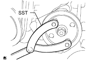
Using SST, hold the pulley and loosen the nut.
- SST
- 09960-10010 ( 09962-01000, 09963-01000 )
-
Remove the nut and vane pump pulley from the vane pump shaft.
-
Remove the 2 bolts and nut and disconnect the vane pump.
Tech Tips
Disconnect the vane pump from the vehicle with the hoses connected, and hang it with a rope.
-
-
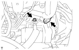
REMOVE CLUTCH RELEASE CYLINDER ASSEMBLY
-
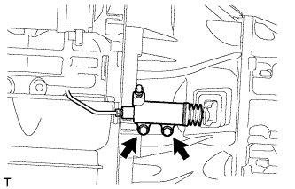
Выверните два болта и отсоедините рабочий цилиндр сцепления.
-
-
REMOVE STARTER ASSEMBLY
-
Disconnect the starter connector.
-
Remove the terminal cap.
-
Remove the nut and disconnect the starter wire.
-
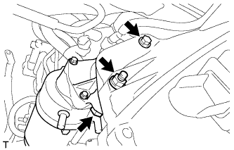
Remove the nut, 2 bolts and starter.
-
-
REMOVE OIL FILTER SUB-ASSEMBLY
-
Using SST, remove the oil filter.
- SST
- 09228-44011
-
-
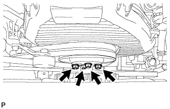
REMOVE FRONT EXHAUST PIPE ASSEMBLY
-
Remove the bolt from the clamp.
-
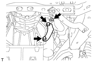
Remove the 2 bolts and No. 1 exhaust pipe support bracket.
-
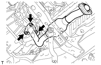
Remove the 3 nuts and front exhaust pipe.
-
Remove the gasket.
-
-
REMOVE FRONT PROPELLER SHAFT ASSEMBLY
-
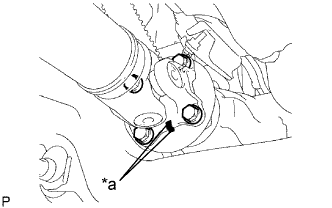
Обозначения на рисунке *a Метка Нанесите метки на фланец карданного вала и дифференциал.
-
Снимите 4 гайки, 4 болта, 4 шайбы и передний карданный вал в сборе.
-
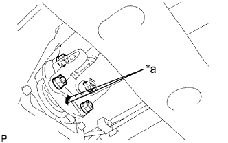
Обозначения на рисунке *a Метка Нанесите метки на фланец карданного вала и фланец раздаточной коробки.
-
Отверните 4 гайки и снимите 4 шайбы и передний карданный вал в сборе.
-
-
REMOVE PROPELLER SHAFT ASSEMBLY
-
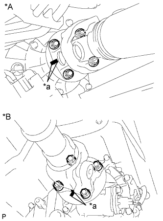
Обозначения на рисунке *A Для 3-дверных моделей *B Для 5-дверных моделей *a Метка Нанесите метки на фланец карданного вала и фланец раздаточной коробки.
-
Отверните 4 гайки и снимите 4 шайбы.
-
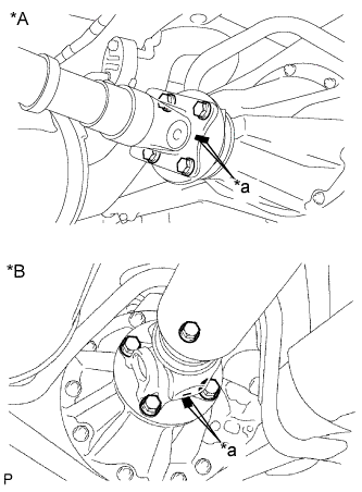
Обозначения на рисунке *A Для 3-дверных моделей *B Для 5-дверных моделей *a Метка Нанесите метки на фланец карданного вала и фланец дифференциала.
-
Отверните 4 гайки и снимите 4 болта и 4 шайбы.
-
Снимите карданный вал.
-
-
REMOVE MANUAL TRANSMISSION ASSEMBLY
-
Remove the manual transmission Click here.
-
-
REMOVE REAR NO. 1 ENGINE MOUNTING INSULATOR
Note
Perform this procedure when replacement of the engine mounting insulator is necessary.
-
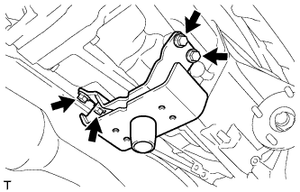
Remove the 4 bolts and rear engine mounting insulator from the transmission.
-
-
REMOVE CLUTCH COVER ASSEMBLY
-
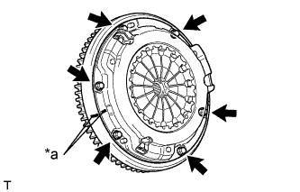
Text in Illustration *a Matchmark Place matchmarks on the clutch cover and flywheel.
-
Loosen each set bolt one turn at a time until spring tension is released.
-
Remove the 6 set bolts and pull off the clutch cover.
Note
Do not drop the clutch disc.
-
-
REMOVE CLUTCH DISC ASSEMBLY
Note
Keep the lining part of the clutch disc, the pressure plate and the surface of the flywheel away from oil and foreign matter.
-
REMOVE FLYWHEEL SUB-ASSEMBLY
-
Using SST, hold the crankshaft.
- SST
- 09213-54015 ( 91651-60855 )
- 09330-00021
-
Remove the 8 bolts and flywheel.
-
-
REMOVE REAR END PLATE
-
Remove the 2 bolts and rear end plate.
-
-
REMOVE FLYWHEEL HOUSING DUST SEAL
-
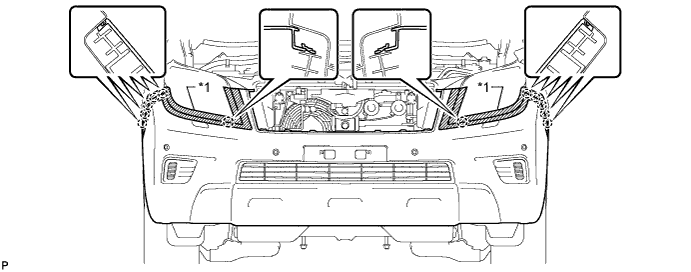
INSTALL ENGINE HANGER
-
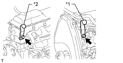
Text in Illustration *1 No. 1 Engine Hanger *2 No. 2 Engine Hanger Install an engine hanger to each location shown in the illustration.
Tech Tips
No. 1 Engine Hanger 12281-54080 No. 2 Engine Hanger 12282-54070 Bolt (No. 1 Engine Hanger) 90119-10736 Bolt (No. 2 Engine Hanger) 91622-61022 - Torque:
- for No. 1 Engine Hanger
- 59 N*m { 602 kgf*cm, 44 ft.*lbf }
- for No. 2 Engine Hanger
- 37 N*m { 377 kgf*cm, 27 ft.*lbf }
Note
Install the engine hangers with new bolts.
-
-
REMOVE ENGINE ASSEMBLY
-
Attach an engine sling device and hang the engine with a chain block.
-
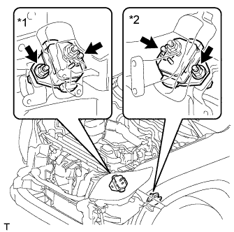
Text in Illustration *1 for RH Side *2 for LH Side Remove the 4 nuts and 4 bolts from the front engine mounting insulator LH and RH.
-
Remove the engine by operating the engine sling device and chain block.
-
-
INSTALL ENGINE TO ENGINE STAND
-
Install the engine to an engine stand with bolts.
-
Remove engine hanger.
-
-
REMOVE ENGINE WIRE
-
Remove the engine wire from the engine.
-
-
REMOVE FRONT ENGINE MOUNTING INSULATOR
-
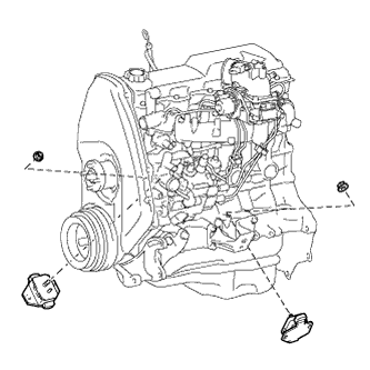
Remove the 2 nuts and 2 front engine mounting insulators.
-