ПРОКЛАДКА ГОЛОВКИ БЛОКА ЦИЛИНДРОВ УСТАНОВКА

-
INSTALL CYLINDER HEAD GASKET
-
Check the piston protrusion for each cylinder.
-
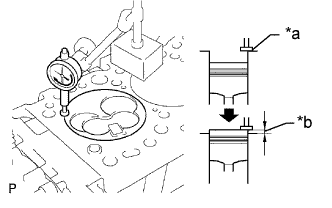
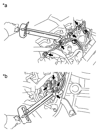
Text in Illustration *a Measuring Tip *b Protrusion Find where the piston head protrudes most by slowly turning the crankshaft clockwise and counterclockwise.
-
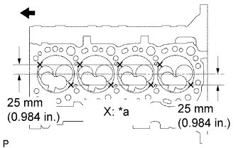
Text in Illustration *a Measuring Point 
Front Measure the protrusion of each cylinder at 2 places as shown in the illustration, making a total of 8 measurements.
-
For the piston protrusion value of each cylinder, use the average of the 2 measurements of that cylinder.
Standard protrusion 0.68 to 0.98 mm (0.0268 to 0.0386 in.) After installing the piston and connecting rod assembly, if the protrusion is not as specified, remove the piston and connecting rod assembly and reinstall them.
-
-
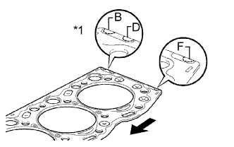
Text in Illustration *1 Cutout Mark Front Select a new cylinder head gasket.
Tech Tips
There are 3 sizes of new cylinder head gaskets, marked "B", "D" or "F" accordingly.
New Cylinder Head Gasket Thickness Item Specified Condition Mark B 1.40 to 1.50 mm (0.0551 to 0.0591 in.) Mark D 1.50 to 1.60 mm (0.0591 to 0.0630 in.) Mark F 1.60 to 1.70 mm (0.0630 to 0.0669 in.)
-
Select the largest piston protrusion value from the measurements made, then select a new appropriate gasket according to the table below.
Gasket Size Piston Protrusion Gasket Size 0.68 to 0.78 mm (0.0268 to 0.0307 in.) Use B 0.78 to 0.88 mm (0.0307 to 0.0346 in.) Use D 0.88 to 0.98 mm (0.0346 to 0.0385 in.) Use F
-
-
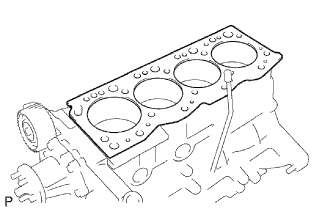
Install the selected cylinder head gasket to the cylinder block.
Note
Make sure that the gasket is installed facing the proper direction.
Be careful of the installation direction.
-
-
INSTALL CYLINDER HEAD SUB-ASSEMBLY
Tech Tips
-
The cylinder head bolts are tightened in 3 progressive steps.
-
Set the No. 1 cylinder to 90° BTDC/compression to avoid interference with the piston top and valve head.
-
If any bolt is broken or deformed, replace it.
-
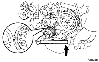
Using the crankshaft pulley bolt, turn the crankshaft 90° counterclockwise, and align the timing mark of the crankshaft timing pulley with the protrusion of the timing belt case.
Text in Illustration Turn -
Place the cylinder head on the cylinder block.
Note
-
Make sure that no oil is on the mounting surface of the cylinder head.
-
Place the cylinder head on the cylinder block gently in order not to damage the gasket with the bottom part of the head.
-
-
Install the plate washers to the cylinder head bolts.
-
Apply a light coat of engine oil to the threads and under the heads of the cylinder head bolts.
-
Step 1:
-
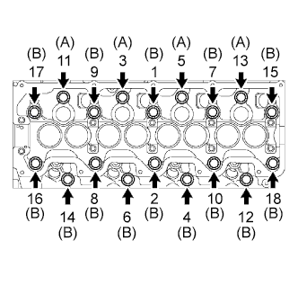
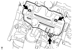
Install and uniformly tighten the 18 cylinder head bolts, in several steps, in the sequence shown in the illustrations.
- Torque:
- 78 N*m { 795 kgf*cm, 58 ft.*lbf }
Tech Tips
Each bolt length is indicated below.
Standard Bolt Item Length Bolt A 107 mm (4.21 in.) Bolt B 127 mm (5.00 in.) If any one of the cylinder head bolts does not meet the torque specification, replace the cylinder set head bolt.
-
-
Step 2:
-
Mark the front side of each cylinder head bolt head with paint.
-
Tighten the cylinder head bolts 90° in the sequence shown in step 1.
-
-
Step 3:
-
Tighten the cylinder head bolts another 90° in the sequence shown in step 1.
-
-
Check that the paint marks are now at a 180° angle to the front.
-
-
INSTALL CYLINDER HEAD COVER SUB-ASSEMBLY
-
Remove any old packing (FIPG material).
-
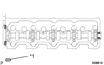
Text in Illustration *1 Seal Packing Apply seal packing to the cylinder head as shown in the illustration.
Seal packing Toyota Genuine Seal Packing Black, Three Bond 1207B or equivalent -
Install the gasket to the cylinder head cover.
-
Install the cylinder head cover with the 9 bolts and nut. Uniformly tighten the bolts and nut in several steps.
- Torque:
- 12 N*m { 122 kgf*cm, 9 ft.*lbf }
-
-
INSTALL WIRING HARNESS CLAMP BRACKET (for LHD)
-
Install the wiring harness clamp bracket with the bolt.
- Torque:
- 22 N*m { 219 kgf*cm, 16 ft.*lbf }
-
-
CONNECT WIRE HARNESS
-
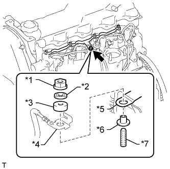
Text in Illustration *1 Nut *2 Washer *3 No. 2 Glow Plug Resistor Insulator *4 Engine Wire *5 No. 1 Glow Plug Connector *6 No. 1 Glow Plug Resistor Insulator *7 Bolt Connect the engine wire and install the No. 2 glow plug resistor insulator and washer with the nut.
- Torque:
- 5.0 N*m { 51 kgf*cm, 44 in.*lbf }
-
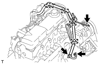
Attach the 4 wire harness clamps.
-
Install the generator wire with the nut.
- Torque:
- 9.8 N*m { 100 kgf*cm, 87 in.*lbf }
-
Install the terminal cap.
-
Connect the generator connector and cooler compressor connector.
-
for RHD:
-
Attach the 5 wire harness clamps.
-
-
for LHD:
-
Attach the 4 wire harness clamps.
-
Attach the 3 wire harness clamps.
-
-
-
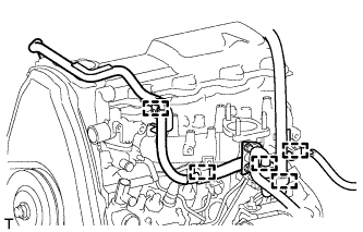
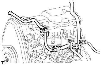
INSTALL INJECTION PIPE SET
-
Install the 2 lower clamps to the intake manifold.
-
Text in Illustration *a for Injection Nozzle Side *b for Injection Pump Side Install the 4 injection pipes.
- Torque:
- 25 N*m { 250 kgf*cm, 18 ft.*lbf }
Note
Use the formula to calculate special torque values for situations where a union nut wrench is combined with a torque wrench Click here.
-
Install the 2 upper pipe clamps with the 2 nuts.
- Torque:
- 5.0 N*m { 51 kgf*cm, 44 in.*lbf }
-
-
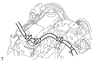
INSTALL HEATER WATER HOSE SUB-ASSEMBLY
-
Connect the 2 water hoses.
-
Install the heater water hose clamp with the bolt.
- Torque:
- 14 N*m { 138 kgf*cm, 10 ft.*lbf }
-
-
INSTALL NO. 1 EXHAUST MANIFOLD HEAT INSULATOR
-
Установите теплозащитный экран и закрепите его 3 болтами.
- Torque:
- Для болта A
- 18 Н*м { 185 кгс*см, 13 фунт-сила-дюймов }
- для болта B
- 19 Н*м { 195 кгс*см, 14 фунт-сила-дюймов }
-
-
INSTALL ENGINE OIL LEVEL DIPSTICK GUIDE
-
Apply a light coat of engine oil to a new O-ring.
-
Install the O-ring to the dipstick guide.
-
Install the dipstick guide with the 2 bolts.
- Torque:
- 18 N*m { 184 kgf*cm, 13 ft.*lbf }
-
Install the dipstick.
-
-
INSTALL NO. 1 COMPRESSOR MOUNTING BRACKET
-
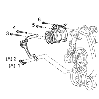
Install the No. 1 compressor mounting bracket with the 4 bolts.
- Torque:
- 81 N*m { 829 kgf*cm, 60 ft.*lbf }
-
Connect the generator with the bolt.
-
-
CONNECT COOLER COMPRESSOR ASSEMBLY
-
Temporarily install the cooler compressor with the 2 bolts.
-
Temporarily install the idle pulley bracket with the 4 bolts.
-
Tighten the 6 bolts in the sequence shown in the illustration.
- Torque:
- for bolt A
- 45 N*m { 459 kgf*cm, 33 ft.*lbf }
- except bolt A
- 25 N*m { 250 kgf*cm, 18 ft.*lbf }
-
Connect the wire harness with the bolt.
- Torque:
- 13 N*m { 131 kgf*cm, 9 ft.*lbf }
-
Connect the cooler compressor connector.
-
-
INSTALL DIESEL THROTTLE BODY ASSEMBLY
-
Install the diesel throttle body Click here.
-
-
INSTALL TIMING BELT
-
Install the timing belt Click here.
-
-
INSTALL FRONT EXHAUST PIPE ASSEMBLY (for Long Wheelbase)
-
Install a new gasket and the front exhaust pipe to the exhaust manifold with 3 new nuts.
- Torque:
- 54 N*m { 554 kgf*cm, 40 ft.*lbf }
-
Install the No. 1 exhaust pipe support bracket with the 2 bolts.
- Torque:
- 71 N*m { 724 kgf*cm, 52 ft.*lbf }
-
Install the clamp with the bolt.
- Torque:
- 19 N*m { 194 kgf*cm, 14 ft.*lbf }
-
-
BLEED AIR FROM FUEL SYSTEM
-
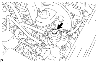
Using the hand pump mounted on the fuel filter cap, bleed the air from the fuel system. Continue pumping until the pump resistance increases.
-
-
ADD ENGINE COOLANT
-
Затяните пробку сливного крана радиатора вручную.
-
Затяните пробку сливного крана блока цилиндров.
- Torque:
- 13 Н*м { 130 кгс*см, 9 фунт-сила-дюймов }
-
Медленно заполните систему охлаждающей жидкостью двигателя.
Номинальный объем 8,6 литра (9,0 кварты США, 7,6 английской кварты) Note
Не доливайте простую воду вместо охлаждающей жидкости двигателя.
Tech Tips
-
Разрешается использовать только охлаждающую жидкость "Toyota Super Long Life Coolant" или аналогичную высококачественную охлаждающую жидкость на основе этиленгликоля (но не на силикатной, аминовой, нитритной или борнокислой основе), изготовленную по гибридной технологии органических кислот с длительным сроком годности (охлаждающая жидкость, изготовленная по гибридной технологии органических кислот, состоит из низкофосфатных соединений и органических кислот.)
-
Новые автомобили Toyota заправлены охлаждающей жидкостью "Toyota Super Long Life Coolant". Для замены рекомендуется использовать охлаждающую жидкость "Toyota Super Long Life Coolant" (розового цвета, предварительно смешанная, с концентрацией этиленгликоля около 50% и температурой замерзания -35°C (-31°F)).
-
-
Медленно залейте охлаждающую жидкость в расширительный бачок радиатора до отметки "FULL".
-
Установите пробку расширительного бачка.
-
Несколько раз сожмите рукой патрубки радиатора № 1 и № 2, а затем проверьте уровень охлаждающей жидкости. Если уровень охлаждающей жидкости недостаточен, добавьте жидкость.
-
Установите на место пробку радиатора.
-
Запустите двигатель и прогрейте его до открывания термостата.
Tech Tips
Время открывания термостата можно распознать, сжав шланг радиатора № 2 рукой и отметив момент, когда охлаждающая жидкость двигателя начнет поступать в шланг.
-
Поддерживайте частоту вращения коленчатого вала двигателя 2000–2500 об/мин.
Note
-
Убедитесь, что в расширительном бачке радиатора осталась охлаждающая жидкость.
-
Обратите внимание на стрелку датчика температуры охлаждающей жидкости. Убедитесь, что значение температуры не превышает норму.
-
В случае недостатка охлаждающей жидкости двигатель может закипеть или перегреться.
-
Если в расширительном бачке радиатора нет охлаждающей жидкости, сразу после запуска двигателя выполните следующие действия: 1) остановите двигатель, 2) подождите, пока охлаждающая жидкость остынет, и 3) долейте охлаждающую жидкость до линии "F".
-
Запустите двигатель, обеспечив частоту вращения коленчатого вала 2000 об/мин, и дайте ему поработать, пока уровень охлаждающей жидкости не стабилизируется.
-
-
Несколько раз сожмите патрубки радиатора № 1 и № 2 рукой, чтобы удалить воздух.
CAUTION:
-
Работайте в защитных перчатках. Нагретые участки деталей могут травмировать руки.
-
Будьте осторожны: патрубки радиатора горячие.
-
Не приближайте свои руки к вентилятору.
-
-
Остановите двигатель и подождите, пока охлаждающая жидкость остынет до температуры окружающего воздуха.
CAUTION:
Не снимайте пробку радиатора, пока двигатель и радиатор не остынут. Выброс горячей охлаждающей жидкости и пара под давлением может стать причиной серьезных ожогов.
-
Убедитесь, что уровень охлаждающей жидкости находится между отметками "LOW" и "FULL".
Если уровень охлаждающей жидкости ниже линии "Low", повторите все вышеперечисленные действия.
Если уровень охлаждающей жидкости выше уровня "FULL", слейте охлаждающую жидкость до уровня между отметками "FULL" и "LOW".
-
-
BLEED INJECTION PIPE
-
Move the hand pump on the upper part of the fuel filter up and down and fill the injection pump and fuel system with fuel.
-
Loosen one of the union nuts (on the nozzle side).
-
Crank the engine until fuel comes out from the union nut connection (on the nozzle side).
-
Tighten the union nut.
- Torque:
- 25 N*m { 250 kgf*cm, 18 ft.*lbf }
Note
Use the formula to calculate special torque values for situations where a union nut wrench is combined with a torque wrench Click here.
-
Perform the procedures above for each injection pipe.
-
-
INSPECT FOR COOLANT LEAK
CAUTION:
To avoid being burned, do not remove the radiator reservoir cap while the engine and radiator are still hot. Thermal expansion may cause hot engine coolant and steam to blow out from the radiator.
-
Fill the radiator with coolant and attach a radiator cap tester to the radiator.
-
Warm up the engine.
-
Using a radiator cap tester, increase the pressure inside the radiator to 123 kPa (1.3 kgf/cm2, 18 psi), and check that the pressure does not drop.
If the pressure drops, check the hoses, radiator or water pump for leaks. If no external leaks are found, check the heater core, cylinder block, and cylinder head.
-
-
INSPECT FOR FUEL LEAK
-
Check that there are no fuel leaks anywhere in the fuel system after performing maintenance.
Tech Tips
When checking for fuel leaks, make sure that there is pressure in the fuel line.
-
-
INSPECT FOR EXHAUST GAS LEAK
-
INSPECT ENGINE IDLE SPEED
-
Warm up the engine.
-
When using the intelligent tester:
-
Connect the intelligent tester to the DLC3.
Idle speed 720 to 820 rpm Note
-
Turn all the electrical systems and the A/C off.
-
When checking the idling speed, the shift lever should be in neutral.
Tech Tips
Refer to the intelligent tester operator's manual for further details.
-
-
-
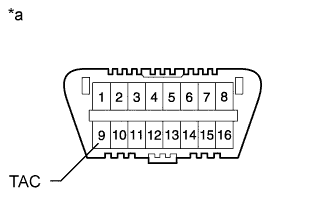
Text in Illustration *a Front View of DLC3 When not using an intelligent tester:
-
Using SST, connect the tachometer test probe to terminal 9 (TAC) of the DLC3.
- SST
- 09843-18040
-
Check the idle speed.
Standard idle speed 720 to 820 rpm Note
-
Turn all the electrical systems and the A/C off.
-
When checking the idling speed, the shift lever should be in neutral.
-
Confirm the terminal number before connecting them. Connecting the wrong terminal can be damage the engine.
-
-
-
-
INSPECT MAXIMUM ENGINE SPEED
-
Start the engine.
-
Fully depress the accelerator pedal.
-
Check the maximum speed.
Maximum engine speed 4850 to 4950 rpm
-