РАСПРЕДВАЛ СНЯТИЕ

-
DISCONNECT CABLE FROM NEGATIVE BATTERY TERMINAL
Note
-
After turning the ignition switch off, waiting time may be required before disconnecting the cable from the battery terminal. Therefore, make sure to read the disconnecting the cable from the battery terminal notice before proceeding with work Click here.
-
When disconnecting the cable, some systems need to be initialized after the cable is reconnected Click here.
-
-
REMOVE UPPER RADIATOR SUPPORT SEAL
-
Освободите 13 фиксаторов и снимите верхнее уплотнение кронштейна радиатора.
-
-
REMOVE FRONT BUMPER COVER LOWER
-
Remove the clip, 5 bolts and front bumper cover lower.
-
-
REMOVE NO. 1 ENGINE UNDER COVER SUB-ASSEMBLY
-
Remove the 4 bolts.
-
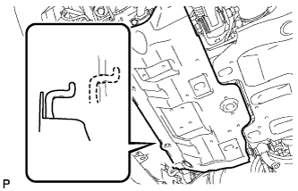
Unhook the engine under cover from the vehicle body as shown in the illustration.
-
-
DRAIN ENGINE COOLANT
CAUTION:
Не снимайте пробку расширительного бачка радиатора, пока двигатель и радиатор не остынут. Выброс горячей охлаждающей жидкости и пара под давлением может стать причиной серьезных ожогов.
-
Ослабьте пробку сливного крана радиатора.
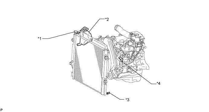
Обозначения на рисунке *1 Пробка радиатора *2 Бачок радиатора *3 Пробка сливного крана радиатора *4 Пробка сливного крана блока цилиндров Tech Tips
Слейте охлаждающую жидкость в контейнер и утилизируйте ее в соответствии с местными требованиями.
-
Слейте охлаждающую жидкость, сняв крышку радиатора.
-
Ослабьте пробку сливного крана блока цилиндров.
-
Ослабьте пробку сливного крана блока цилиндров и слейте охлаждающую жидкость из двигателя.
Note
Если охлаждающая жидкость не сливается через пробку сливного крана радиатора, пробки сливных кранов блока цилиндров и расширительный бачок радиатора, возможны засорение радиатора и утечка охлаждающей жидкости через уплотнение насоса системы охлаждения.
-
-
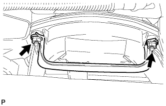
REMOVE FRONT FENDER APRON SEAL RH
-
Remove the 4 clips and fender apron seal.
-
-
REMOVE RESONATOR WITH AIR CLEANER CAP SUB-ASSEMBLY
-
Disconnect the sensor connector.
-
Detach the wire harness clamp.
-
Loosen the hose clamp and remove the resonator with air cleaner cap.
-
Detach the 4 hook clamps, and then remove the air cleaner cap and resonator with air cleaner cap.
-
-
REMOVE AIR CLEANER FILTER ELEMENT SUB-ASSEMBLY
-
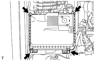
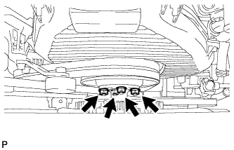
REMOVE AIR CLEANER CASE ASSEMBLY
-
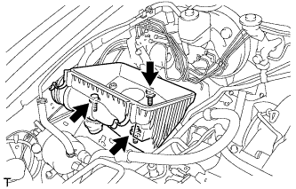
Remove the 3 bolts and air cleaner case.
-
-
DISCONNECT WIRE HARNESS
-
Remove the terminal cap.
-
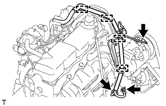
Remove the nut and generator wire.
-
Disconnect the generator connector and cooler compressor connector.
-
Detach the 4 wire harness clamps.
-
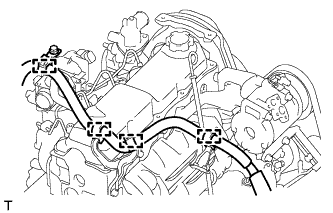
for LHD:
Detach the 4 wire harness clamps.
-
-
REMOVE WIRING HARNESS CLAMP BRACKET (for LHD)
-
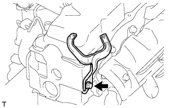
Remove the bolt and wiring harness clamp bracket.
-
-
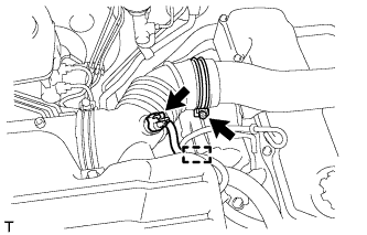
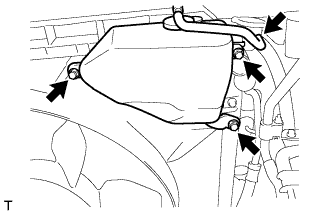
REMOVE NO. 1 RADIATOR HOSE
-
Detach the clamp and remove the No. 1 radiator hose.
-
Remove the 2 nuts and hose clamp.
-
-
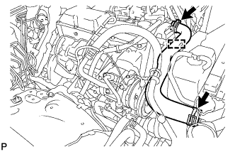
REMOVE RADIATOR RESERVE TANK ASSEMBLY
-
Disconnect the reservoir hose from the upper side of the radiator tank.
-
Remove the 3 bolts and radiator reservoir.
-
-
REMOVE FAN SHROUD
-
Loosen the 4 nuts holding the fluid coupling fan.
-
Remove the vane pump V belt and the fan and generator V belt Click here.
-
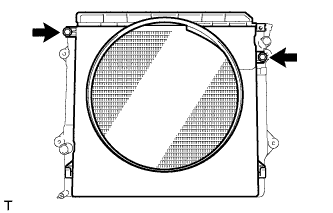
Remove the 2 bolts holding the fan shroud.
-
Remove the 4 nuts of the fluid coupling fan, and then remove the shroud together with the coupling fan.
Note
Be careful not to damage the radiator core.
-
Remove the fan pulley from the water pump.
-
-
REMOVE VANE PUMP DRIVE PULLEY
-
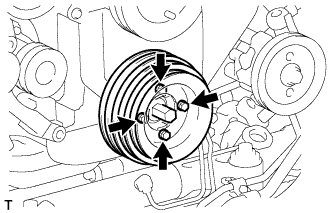
Remove the 4 bolts, vane pump drive pulley and cooler compressor drive pulley.
-
-
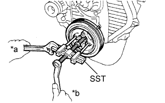
REMOVE CRANKSHAFT PULLEY

Text in Illustration *a Hold *b Turn
-
Using SST, remove the pulley bolt.
- SST
- 09213-54015 ( 91651-60855 )
- 09330-00021
-
Text in Illustration *a Hold *b Turn Using SST, remove the pulley.
- SST
- 09950-50013 ( 09951-05010, 09952-05010, 09953-05020, 09954-05021 )
- 09950-60010 ( 09951-00490 )
- 09950-40011 ( 09957-04010 )
-
-
REMOVE IDLE PULLEY ASSEMBLY
-
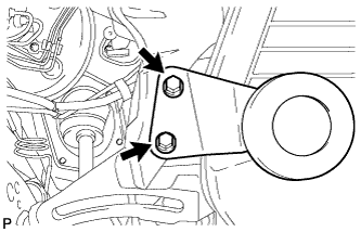
Remove the 2 bolts and Idle pulley bracket.
-
-
REMOVE TIMING BELT COVER
-
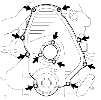
Remove the 11 bolts, washers, timing belt cover, and 2 gaskets.
-
-
REMOVE TIMING BELT GUIDE
-
Remove the timing belt guide.
-
-
SET NO. 1 CYLINDER TO TDC/COMPRESSION
Tech Tips
If reusing the timing belt, draw a direction arrow on the timing belt (in the direction the belt move when the engine is running), and place matchmarks on the pulleys and timing belt.
-
Turn the crankshaft 90° counterclockwise, and align the timing mark of the crankshaft timing pulley with the protrusion of the timing belt case.
Text in Illustration 
Turn Note
If the timing belt is disengaged, having the crankshaft timing pulley at the wrong angle can cause the piston head and valve head to come into contact with each other when removing the camshaft timing pulley, and camshaft causing damage. Therefore, always set the crankshaft pulley is removed at the correct angle.
-
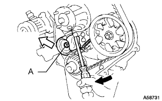
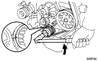
Loosen the No. 1 timing belt idler bolt (A), and shift the idler to the left as far as possible.
Text in Illustration Pry 
Move -
Tighten the No. 1 timing belt idler bolt (A), and then relieve the timing belt tension.
-
Remove the timing belt.
-
-
REMOVE TIMING BELT
Tech Tips
If reusing the timing belt, draw a direction arrow on the timing belt (in the direction the belt move when the engine is running), and place matchmarks on the pulleys and timing belt.
-
Turn the crankshaft 90° counterclockwise, and align the timing mark of the crankshaft timing pulley with the protrusion of the timing belt case.
Text in Illustration Turn Note
If the timing belt is disengaged, having the crankshaft timing pulley at the wrong angle can cause the piston head and valve head to come into contact with each other when removing the camshaft timing pulley, and camshaft causing damage. Therefore, always set the crankshaft pulley is removed at the correct angle.
-
Loosen the No. 1 timing belt idler bolt (A), and shift the idler to the left as far as possible.
Text in Illustration Pry Move -
Tighten the No. 1 timing belt idler bolt (A), and then relieve the timing belt tension.
-
Remove the timing belt.
-
-
REMOVE INTAKE PIPE
-
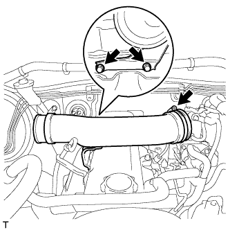
Loosen the hose clamp and remove the 2 bolts and intake pipe.
-
-
REMOVE CYLINDER HEAD COVER SUB-ASSEMBLY
-
Remove the 9 bolts, nut, cylinder head cover and gasket.
-
-
REMOVE CAMSHAFT TIMING PULLEY
-
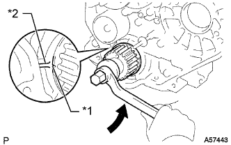
Text in Illustration Turn *1 Timing Mark *2 Protrusion Using the crankshaft pulley bolt, turn the crankshaft 90° counterclockwise and align the timing mark of the crankshaft timing pulley with the protrusion of the timing belt case.
Tech Tips
Set the No. 1 cylinder to 90° BTDC/compression to avoid interference with the piston top and valve head.
-
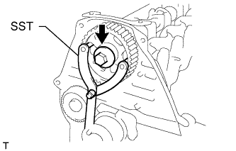
Using SST, loosen the pulley bolt.
- SST
- 09960-10010 ( 09962-01000, 09963-01000 )
-
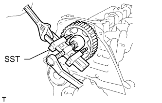
Using SST, separate the timing pulley from the camshaft.
- SST
- 09950-50013 ( 09951-05010, 09952-05010, 09953-05010, 09954-05021 )
-
Remove the pulley bolt and timing pulley.
-
Remove the timing pulley woodruff key.
-
-
REMOVE NO. 2 TIMING BELT COVER
-
Remove the 4 bolts and timing belt cover.
-
-
REMOVE CAMSHAFT OIL SEAL RETAINER
-
Remove the 4 bolts, retainer and gasket.
-
-
REMOVE CAMSHAFT OIL SEAL
-
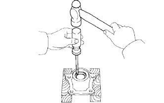
Using a screwdriver and hammer, tap out the oil seal.
-
-
REMOVE CAMSHAFT
-
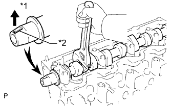
Text in Illustration *1 Upward *2 Key Groove Turn the camshaft with a wrench so that the key groove faces upward.
-
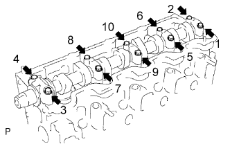
Uniformly loosen and remove the 10 bearing cap bolts in several steps in the sequence shown in the illustration.
-
Remove the 5 bearing caps and camshaft.
Tech Tips
Arrange the bearing caps in the correct order.
-