СИСТЕМА ECD Starter Signal Circuit
DESCRIPTION
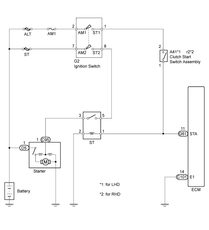
When the engine is cranked, the intake air flow becomes slow so fuel vaporization is poor. A rich mixture is therefore necessary in order to achieve good startability. While the engine is being cranked, the battery voltage is applied to terminal STA of the ECM. The starter signal is mainly used to increase the fuel injection volume for starting and after-start injection control.
WIRING DIAGRAM
INSPECTION PROCEDURE
When using intelligent tester:
PROCEDURE
-
READ VALUE USING INTELLIGENT TESTER
-
Connect the intelligent tester to the DLC3.
-
Turn the ignition switch to ON and turn the tester on.
-
Enter the following menus: Powertrain / Engine and ECT / Data List / Starter Signal.
-
Read the STA signal on the intelligent tester while the starter operates.
OK Ignition Switch Position Starter SIG LOCK, ACC, ON OFF START ON
NG 
CHECK HARNESS AND CONNECTOR (CLUTCH START SWITCH - ECM) Click here
OK 
PROCEED TO NEXT SUSPECTED AREA SHOWN IN PROBLEM SYMPTOMS TABLE Click here
-
-
CHECK HARNESS AND CONNECTOR (CLUTCH START SWITCH - ECM)
-
Disconnect the clutch start switch connector.
-
Disconnect the ECM connector.
-
Measure the resistance according to the value(s) in the table below.
Standard Resistance (Check for Open) for LHD Tester Connection Condition Specified Condition A41-1 - G61-11 (STA) Always Below 1 Ω for RHD Tester Connection Condition Specified Condition r2-1 - G61-11 (STA) Always Below 1 Ω Standard Resistance (Check for Short) for LHD Tester Connection Condition Specified Condition A41-1 or G61-11 (STA) - Body ground Always 10 kΩ higher for RHD Tester Connection Condition Specified Condition r2-1 or G61-11 (STA) - Body ground Always 10 kΩ higher -
Reconnect the clutch start switch connector.
-
Reconnect the ECM connector.
NG 
REPAIR OR REPLACE HARNESS OR CONNECTOR
OK
REPLACE ECM Click here
-
When not using intelligent tester:
PROCEDURE
-
CHECK ECM
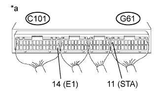
Text in Illustration *a Component with harness connected
(ECM)
-
Turn the ignition switch to ON.
-
Measure the voltage according to the value(s) in the table below.
Standard Voltage Tester Connection Condition Specified Condition G61-11 (STA) - C101-14 (E1) Cranking 6 V or higher
NG
CHECK HARNESS AND CONNECTOR (CLUTCH START SWITCH - ECM) Click here
OK
PROCEED TO NEXT SUSPECTED AREA SHOWN IN PROBLEM SYMPTOMS TABLE Click here
-
-
CHECK HARNESS AND CONNECTOR (CLUTCH START SWITCH - ECM)
-
Disconnect the clutch start switch connector.
-
Disconnect the ECM connector.
-
Measure the resistance according to the value(s) in the table below.
Standard Resistance (Check for Open) for LHD Tester Connection Condition Specified Condition A41-1 - G61-11 (STA) Always Below 1 Ω for RHD Tester Connection Condition Specified Condition r2-1 - G61-11 (STA) Always Below 1 Ω Standard Resistance (Check for Short) for LHD Tester Connection Condition Specified Condition A41-1 or G61-11 (STA) - Body ground Always 10 kΩ higher for RHD Tester Connection Condition Specified Condition r2-1 or G61-11 (STA) - Body ground Always 10 kΩ higher -
Reconnect the clutch start switch connector.
-
Reconnect the ECM connector.
NG
REPAIR OR REPLACE HARNESS OR CONNECTOR
OK
REPLACE ECM Click here
-