СИСТЕМА ECD, Diagnostic DTC:19 (2)
| DTC Code | DTC Name |
|---|---|
| 19 (2) | Accelerator Position Sensor Range / Performance Problem |
DESCRIPTION
Refer to DTC 19 (1) Click here.
| DTC No. | DTC Detection Condition | Trouble Area |
|---|---|---|
| 19 (2) | Either of the ECM sensors has completed learning, and the voltage difference of the No. 1 and No. 2 sensors is more than 1.2 V or less than 0.4 V. |
|
| One of the following continues for more than 2.0 seconds.
|
WIRING DIAGRAM
Refer to DTC 19 (1) Click here.
INSPECTION PROCEDURE
Tech Tips
Read freeze frame data using the intelligent tester. Freeze frame data records the engine condition when malfunctions are detected. When troubleshooting, freeze frame data can help determine if the vehicle was moving or stationary, if the engine was warmed up or not, and other data from the time the malfunction occurred.
When using intelligent tester:
PROCEDURE
-
READ VALUE USING INTELLIGENT TESTER (ACCELERATOR POSITION)
-
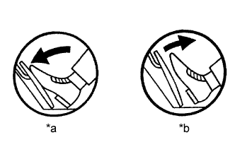
Text in Illustration *a Depressed *b Released Connect the intelligent tester to the DLC3.
-
Turn the ignition switch to ON.
-
Enter the following menus: Powertrain / Engine and ECT / Data List / Accel Position.
-
Check that the value displayed on the intelligent tester changes when repeatedly depressing and releasing the accelerator pedal.
OK Value changes.
NG 
OK 
REPLACE ECM Click here
-
-
CHECK HARNESS AND CONNECTOR (ECM - ACCELERATOR PEDAL POSITION SENSOR)
-
Disconnect the accelerator pedal position sensor connector.
-
Disconnect the ECM connector.
-
Measure the resistance according to the value(s) in the table below.
Standard Resistance (Check for Open) Tester Connection Condition Specified Condition A19-1 (VCP2) - C102-1 (VC) Always Below 1 Ω A19-2 (EPA2) - C102-9 (E2) Always Below 1 Ω A19-3 (VPA2) - G62-12 (VPA2) Always Below 1 Ω A19-4 (VCPA) - G62-6 (VCPA) Always Below 1 Ω A19-5 (EPA) - G62-4 (EPA) Always Below 1 Ω A19-6 (VPA) - G62-5 (VPA) Always Below 1 Ω Standard Resistance (Check for Short) Tester Connection Condition Specified Condition A19-1 (VCP2) or C102-1 (VC) - Body ground Always 10 kΩ or higher A19-2 (EPA2) or C102-9 (E2) - Body ground Always 10 kΩ or higher A19-3 (VPA2) or G62-12 (VPA2) - Body ground Always 10 kΩ or higher A19-4 (VCPA) or G62-6 (VCPA) - Body ground Always 10 kΩ or higher A19-5 (EPA) or G62-4 (EPA) - Body ground Always 10 kΩ or higher A19-6 (VPA) or G62-5 (VPA) - Body ground Always 10 kΩ or higher -
Reconnect the accelerator pedal position sensor connector.
-
Reconnect the ECM connector.
NG 
REPAIR OR REPLACE HARNESS OR CONNECTOR
OK
REPLACE ACCELERATOR PEDAL ROD ASSEMBLY Click here
-
When not using intelligent tester:
PROCEDURE
-
CHECK ECM (VPA, VPA2 VOLTAGE)
-
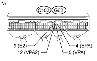
Text in Illustration *a Component with harness connected
(ECM)
Turn the ignition switch to ON.
-
Measure the voltage according to the value(s) in the table below.
Standard Voltage Accelerator Pedal Released Tester Connection Switch Condition Specified Condition G62-5 (VPA) - G62-4 (EPA) Ignition switch ON 0.5 to 1.1 V G62-12 (VPA2) - C102-9 (E2) Ignition switch ON 1.2 to 2.0 V Accelerator Pedal Depressed Tester Connection Switch Condition Specified Condition G62-5 (VPA) - G62-4 (EPA) Ignition switch ON 2.6 to 4.5 V G62-12 (VPA2) - C102-9 (E2) Ignition switch ON 3.4 to 5.3 V
NG
OK
REPLACE ECM Click here
-
-
CHECK HARNESS AND CONNECTOR (ECM - ACCELERATOR PEDAL POSITION SENSOR)
-
Disconnect the accelerator pedal position sensor connector.
-
Disconnect the ECM connector.
-
Measure the resistance according to the value(s) in the table below.
Standard Resistance (Check for Open) Tester Connection Condition Specified Condition A19-1 (VCP2) - C102-1 (VC) Always Below 1 Ω A19-2 (EPA2) - C102-9 (E2) Always Below 1 Ω A19-3 (VPA2) - G62-12 (VPA2) Always Below 1 Ω A19-4 (VCPA) - G62-6 (VCPA) Always Below 1 Ω A19-5 (EPA) - G62-4 (EPA) Always Below 1 Ω A19-6 (VPA) - G62-5 (VPA) Always Below 1 Ω Standard Resistance (Check for Short) Tester Connection Condition Specified Condition A19-1 (VCP2) or C102-1 (VC) - Body ground Always 10 kΩ or higher A19-2 (EPA2) or C102-9 (E2) - Body ground Always 10 kΩ or higher A19-3 (VPA2) or G62-12 (VPA2) - Body ground Always 10 kΩ or higher A19-4 (VCPA) or G62-6 (VCPA) - Body ground Always 10 kΩ or higher A19-5 (EPA) or G62-4 (EPA) - Body ground Always 10 kΩ or higher A19-6 (VPA) or G62-5 (VPA) - Body ground Always 10 kΩ or higher -
Reconnect the accelerator pedal position sensor connector.
-
Reconnect the ECM connector.
NG
REPAIR OR REPLACE HARNESS OR CONNECTOR
OK
REPLACE ACCELERATOR PEDAL ROD ASSEMBLY Click here
-