СИСТЕМА ECD, Diagnostic DTC:14 (4)
| DTC Code | DTC Name |
|---|---|
| 14 (4) | Timing Control System Malfunction |
DESCRIPTION
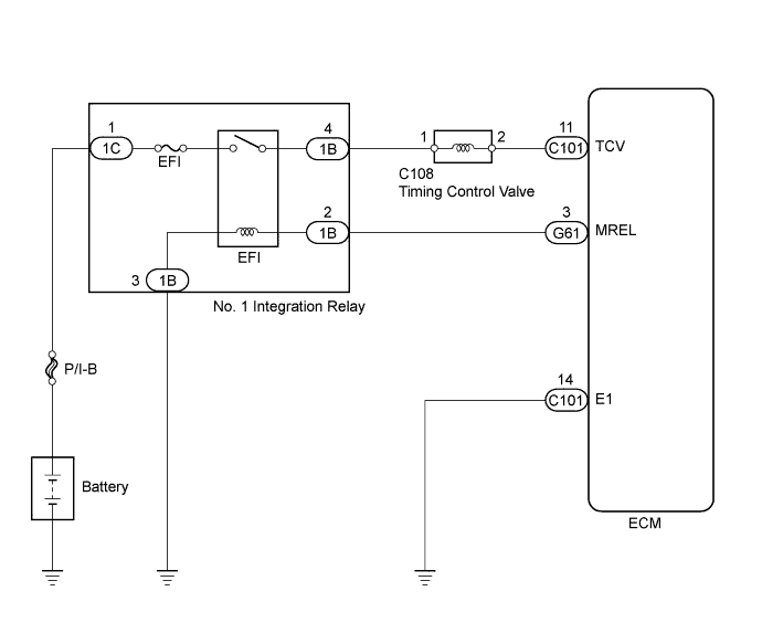
The ECM controls the injection timing by actuating the timing control valve. The timing control valve is mounted on the injection pump and controls the internal fuel pressure of the pump through duty control.
The ECM detects the injection advance angle based on TDC and NE signals.
| DTC No. | DTC Detection Condition | Trouble Area |
|---|---|---|
| 14 (4) | During and after warming up the engine, the actual injection timing is different from the target value that the ECM calculated for several seconds. |
|
WIRING DIAGRAM
INSPECTION PROCEDURE
PROCEDURE
-
INSPECT TIMING CONTROL VALVE
-
Inspect the timing control valve Click here.
NG 
REPLACE TIMING CONTROL VALVE Click here
OK 
-
-
CHECK ECM (TCV VOLTAGE)
-
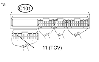
Text in Illustration *a Rear view of wire harness connector
(to ECM)
Disconnect the ECM connector.
-
Turn the ignition switch to ON.
-
Measure the voltage according to the value(s) in the table below.
Standard Voltage Tester Connection Switch Condition Specified Condition C101-11 (TCV) - Body ground Ignition switch ON 11 to 14 V -
Reconnect the ECM connector.
NG 
CHECK TIMING CONTROL VALVE (POWER SOURCE) Click here
OK
-
-
CHECK ECM (TCV VOLTAGE, SIGNAL)
-
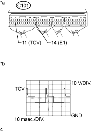
Text in Illustration *a Component with harness connected
(ECM)
*b TCV Signal Waveform Turn the ignition switch to ON.
-
Measure the voltage according to the value(s) in the table below.
Standard Voltage Tester Connection Switch Condition Specified Condition C101-11 (TCV) - C101-14 (E1) Ignition switch ON 11 to 14 V -
While idling, check the waveform according to the value(s) in the table below.
OK Tester Connection Condition Specified Condition C101-11 (TCV) - C101-14 (E1) Idling Correct waveform is as shown
NG
REPLACE ECM Click here
OK
-
-
CHECK LEVEL WARNING SWITCH
-
Check the level warning switch Click here.
NG
REPLACE LEVEL WARNING SWITCH Click here
OK
-
-
CHECK FOR FUEL LEAK
-
Visually check the injection pump, each injector and the fuel line for fuel leaks.
OK No leakage.
NG
REPAIR OR REPLACE PART WITH FUEL LEAKAGE
OK 
REPLACE INJECTION PUMP ASSEMBLY Click here
-
-
CHECK TIMING CONTROL VALVE (POWER SOURCE)
-

Text in Illustration *a Front view of wire harness connector
(to Timing control valve)
Disconnect the timing control valve connector.
-
Turn the ignition switch to ON.
-
Measure the voltage according to the value(s) in the table below.
Standard Voltage Tester Connection Switch Condition Specified Condition C108-1 - Body ground Ignition switch ON 11 to 14 V -
Reconnect the timing control valve connector.
NG
CHECK HARNESS AND CONNECTOR (TIMING CONTROL VALVE - NO. 1 INTEGRATION RELAY (EFI)) Click here
OK
REPAIR OR REPLACE HARNESS OR CONNECTOR (TIMING CONTROL VALVE - ECM)
-
-
CHECK HARNESS AND CONNECTOR (TIMING CONTROL VALVE - NO. 1 INTEGRATION RELAY (EFI))
-
Disconnect the timing control valve connector.
-
Disconnect the No. 1 integration relay (EFI) connector from the engine room junction block.
-
Measure the resistance according to the value(s) in the table below.
Standard Resistance (Check for Open) Tester Connection Condition Specified Condition C108-1 - 1B-4 Always Below 1 Ω Standard Resistance (Check for Short) Tester Connection Condition Specified Condition C108-1 or 1B-4 - Body ground Always 10 kΩ or higher -
Reconnect the timing control valve connector.
-
Reconnect the No. 1 integration relay (EFI) connector.
NG
REPAIR OR REPLACE HARNESS OR CONNECTOR
OK
CHECK ECM POWER SOURCE CIRCUIT Click here
-