- Click here
INSTALL 3RD GEAR NEEDLE ROLLER BEARING
-
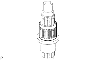
Coat the needle roller bearing with gear oil and install it to the output shaft.
-
- Click here
INSTALL 3RD GEAR
-
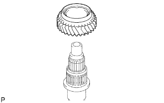
Coat the 3rd gear with gear oil and install it to the output shaft.
-
- Click here
INSTALL NO. 1 SYNCHRONIZER RING
-
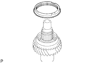
Coat the No. 1 synchronizer ring with gear oil and install it to the 3rd gear.
-
- Click here
INSTALL NO. 2 TRANSMISSION CLUTCH HUB
-
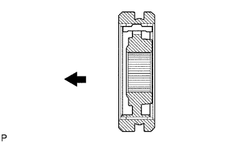
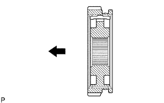
Coat the hub sleeve with gear oil and install it to the clutch hub.
Table 1. Text in Illustration 
Front Note:Be sure to install the hub sleeve to the clutch hub in the correct direction.
-
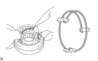
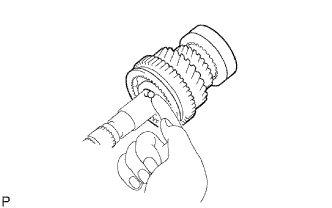
Install the 3 synchromesh shifting keys to the clutch hub with the 2 synchromesh shifting key springs.
Note:Do not set both openings of the shifting key springs in the same position.
-
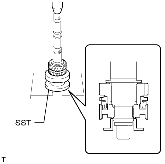
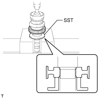
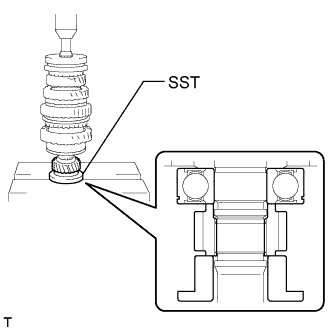
Using SST and a press, install the No. 2 clutch hub to the output shaft.
09316-60011 09316-00021 -
Select a clutch hub shaft snap ring that will allow minimal axial play.
Standard clearance 0.10 mm (0.00394 in.) or less Standard Clutch Hub Shaft Snap Ring Mark Thickness C-1 1.75 to 1.80 mm (0.0689 to 0.0709 in.) D 1.80 to 1.85 mm (0.0709 to 0.0728 in.) D-1 1.85 to 1.90 mm (0.0728 to 0.0748 in.) E 1.90 to 1.95 mm (0.0748 to 0.0768 in.) E-1 1.95 to 2.00 mm (0.0768 to 0.0787 in.) F 2.00 to 2.05 mm (0.0787 to 0.0807 in.) F-1 2.05 to 2.10 mm (0.0807 to 0.0827 in.) -
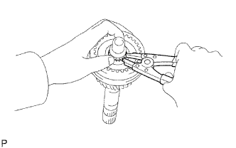
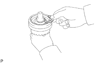
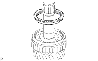
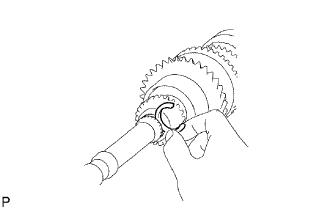
Using a snap ring expander, install the snap ring.
-
- Click here
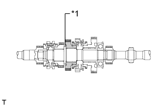
INSPECT 3RD GEAR THRUST CLEARANCE
-
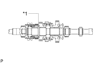
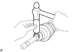
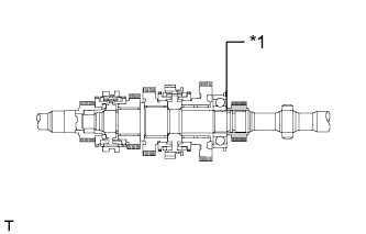
Using a feeler gauge, measure the thrust clearance.
Standard clearance 0.10 to 0.25 mm (0.00394 to 0.00984 in.) Table 2. Text in Illustration *1 3rd Gear
-
If the result is not as specified, replace the No. 2 synchronizer ring set.
-
-
- Click here
INSTALL 2ND GEAR NEEDLE ROLLER BEARING
-
Coat the needle roller bearing with gear oil and install it to the output shaft.
-
- Click here
INSTALL 2ND GEAR
-
Coat the 2nd gear with gear oil and install it to the output shaft.
-
- Click here
INSTALL NO. 2 SYNCHRONIZER RING (for 2nd Gear)
-
Coat the No. 2 synchronizer ring with gear oil and install it to the 2nd gear.
-
- Click here
INSTALL NO. 1 TRANSMISSION CLUTCH HUB
-
Coat the reverse gear with gear oil and install it to the clutch hub.
Table 3. Text in Illustration Front Note:Be sure to install the reverse gear to the clutch hub in the correct direction.
-
Install the 3 synchromesh shifting keys to the clutch hub with the 2 synchromesh shifting key springs.
Note:Do not set both openings of the shifting key springs in the same position.
-
Using SST and a press, install the clutch hub to the output shaft.
09316-60011
-
- Click here
INSTALL NO. 1 SYNCHRONIZER RING (for 1st Gear)
-
Coat the synchronizer ring with gear oil and install it to the No. 1 clutch hub.
-
- Click here
INSTALL 1ST GEAR BEARING INNER RACE LOCK BALL
-
Coat the lock ball with gear oil and install it to the output shaft.
-
- Click here
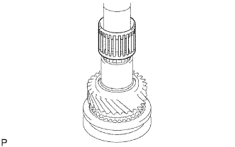
INSTALL 1ST GEAR BEARING INNER RACE
-
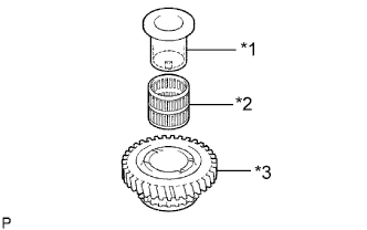
Coat the needle roller bearing with gear oil.
-
Install the inner race and needle roller bearing to the 1st gear.
Table 4. Text in Illustration *1 1st Gear Bearing Inner Race *2 1st Gear Needle Roller Bearing *3 1st Gear
-
- Click here
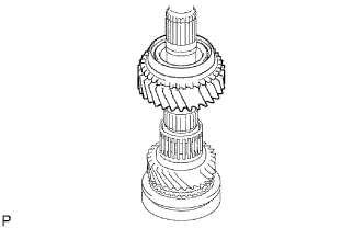
INSTALL 1ST GEAR
-
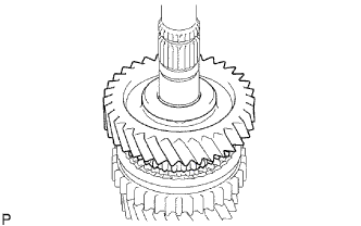
Coat the 1st gear with gear oil and install it to the output shaft.
-
- Click here
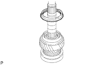
INSTALL OUTPUT SHAFT CENTER BEARING
-
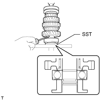
Using SST and a press, install the center bearing to the output shaft.
09316-60011 09316-00021
-
- Click here
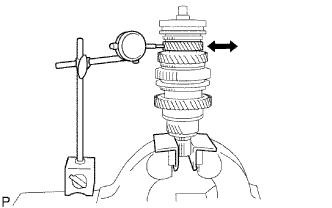
INSPECT 1ST GEAR THRUST CLEARANCE
-
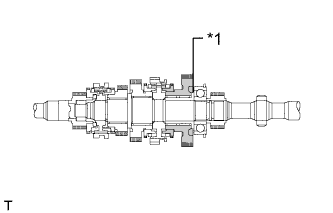
Using a dial indicator, measure the thrust clearance.
Standard clearance 0.10 to 0.25 mm (0.00394 to 0.00984 in.) Table 5. Text in Illustration *1 1st Gear
-
If the result is not as specified, replace the No. 1 synchronizer ring set.
-
-
- Click here
INSTALL 5TH GEAR
-
Using SST and a press, install the 5th gear to the output shaft.
09316-60011 09316-00021 -
Select a snap ring that will allow minimal axial play.
Standard clearance 0.10 mm (0.00394 in.) or less Standard Output Shaft Bearing Shaft Snap Ring Mark Thickness A 2.67 to 2.72 mm (0.1052 to 0.1070 in.) B 2.73 to 2.78 mm (0.1075 to 0.1094 in.) C 2.79 to 2.84 mm (0.1099 to 0.1118 in.) D 2.85 to 2.90 mm (0.1123 to 0.1141 in.) E 2.91 to 2.96 mm (0.1146 to 0.1165 in.) F 2.97 to 3.02 mm (0.1170 to 0.1188 in.) G 3.03 to 3.08 mm (0.1193 to 0.1212 in.) H 3.09 to 3.14 mm (0.1217 to 0.1236 in.) J 3.15 to 3.20 mm (0.1241 to 0.1259 in.) K 3.21 to 3.26 mm (0.1264 to 0.1283 in.) L 3.27 to 3.32 mm (0.1288 to 0.1307 in.) -
Using a brass bar and hammer, tap on the snap ring.
-
- Click here
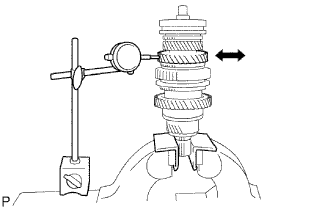
INSPECT 5TH GEAR THRUST CLEARANCE
-
Using a dial indicator, measure the thrust clearance.
Standard clearance 0.10 to 0.30 mm (0.00394 to 0.0118 in.) Table 6. Text in Illustration *1 5th Gear
-
If the result is not as specified, replace the 5th gear.
-
-
- Click here
INSPECT 3RD GEAR THRUST CLEARANCE
-
Using a feeler gauge, measure the thrust clearance.
Standard clearance 0.10 to 0.25 mm (0.00394 to 0.00984 in.) Table 7. Text in Illustration *1 3rd Gear
-
If the result is not as specified, replace the No. 2 synchronizer ring set.
-
-
- Click here
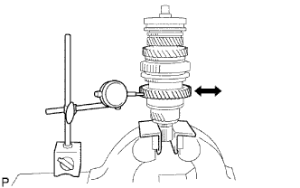
INSPECT 2ND GEAR THRUST CLEARANCE
-
Using a dial indicator, measure the thrust clearance.
Standard clearance 0.10 to 0.25 mm (0.00394 to 0.00984 in.) Table 8. Text in Illustration *1 2nd Gear
-
If the result is not as specified, replace the No. 1 synchronizer ring set.
-
-
- Click here
INSPECT 1ST GEAR THRUST CLEARANCE
-
Using a dial indicator, measure the thrust clearance.
Standard clearance 0.10 to 0.25 mm (0.00394 to 0.00984 in.) Table 9. Text in Illustration *1 1st Gear
-
If the result is not as specified, replace the No. 1 synchronizer ring set.
-
-
- Click here
INSPECT 3RD GEAR RADIAL CLEARANCE
-
Using a dial indicator, measure the radial clearance.
Standard clearance 0.008 to 0.034 mm (0.000315 to 0.00133 in.)
-
If the result is not as specified, replace the 3rd gear needle roller bearing.
-
-
- Click here
INSPECT 2ND GEAR RADIAL CLEARANCE
-
Using a dial indicator, measure the radial clearance.
Standard clearance 0.008 to 0.034 mm (0.000315 to 0.00133 in.)
-
If the result is not as specified, replace the 2nd gear needle roller bearing.
-
-
- Click here
INSPECT 1ST GEAR RADIAL CLEARANCE
-
Using a dial indicator, measure the radial clearance.
Standard clearance 0.009 to 0.056 mm (0.000355 to 0.00220 in.)
-
If the result is not as specified, replace the 1st gear needle roller bearing.
-
-