REAR BUMPER REASSEMBLY

-
INSTALL REAR BUMPER PROTECTOR LH (for LHD)
-
Install the rear bumper protector LH.
-
-
INSTALL REAR BUMPER PROTECTOR RH (for LHD)
Tech Tips
Use the same procedure as for the LH side.
-
INSTALL REAR BUMPER BAR LH
-
Engage the 3 claws to install the rear bumper bar LH.
-
-
INSTALL REAR BUMPER BAR RH
Tech Tips
Use the same procedure as for the LH side.
-
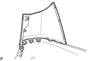
INSTALL REAR BUMPER SIDE SUPPORT LH
-
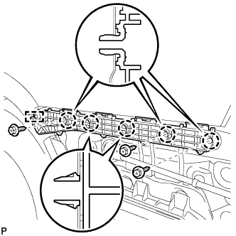
Engage the guide and 5 claws.
-
Install the rear bumper side support LH with the 3 screws.
-
-
INSTALL REAR BUMPER SIDE SUPPORT RH
Tech Tips
Use the same procedure as for the LH side.
-
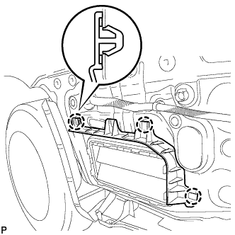
INSTALL NO. 1 REAR BUMPER SIDE SUPPORT LH
-
Engage the 3 claws.
-
Install the No. 1 rear bumper side support LH with the 2 screws.
-
-
INSTALL NO. 1 REAR BUMPER SIDE SUPPORT RH
Tech Tips
Use the same procedure as for the LH side.
-
INSTALL NO. 1 REAR BUMPER PLATE
-
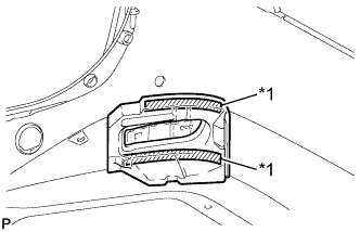
Text in Illustration *1 Hook Engage the hook.
-
Engage the 2 claws to install the No. 1 rear bumper plate to the rear bumper cover.
Tech Tips
Use the same procedure for the RH side and LH side.
-
-
INSTALL REAR BUMPER ENERGY ABSORBER LH (w/ Energy Absorber)
-
Clean the rear bumper cover surface.
-
Remove the double-sided tape from the rear bumper cover.
-
Wipe off any tape adhesive residue with cleaner.
-
-
Clean the rear bumper energy absorber LH (if reusing the rear bumper energy absorber LH)
Note
Make sure that the rear bumper energy absorber LH is not deformed. If it is, replace it with a new one.
-
Remove the double-sided tape from the rear bumper energy absorber LH.
-
Wipe off any tape adhesive residue with cleaner.
-
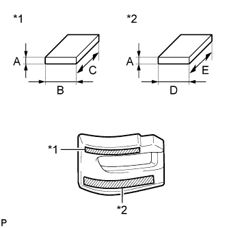
Text in Illustration *1 Double-sided Tape (A) *2 Double-sided Tape (B) Apply new double-sided tape to the rear bumper energy absorber LH.
Item Dimension A 2.0 mm (0.0787 in.) B 15.0 mm (0.591 in.) C 160.0 mm (6.30 in.) D 20.0 mm (0.787 in.) E 210.0 mm (8.27 in.)
-
-
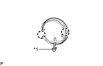
Remove the release paper from the rear bumper energy absorber LH.
Tech Tips
After removing the release paper, keep the exposed adhesive free from foreign matter.
-
Text in Illustration *1 Double-sided Tape Install the rear bumper energy absorber LH.
-
-
INSTALL REAR BUMPER ENERGY ABSORBER RH (w/ Energy Absorber)
Tech Tips
Use the same procedure as for the LH side.
-
INSTALL REFLEX REFLECTOR ASSEMBLY LH
-
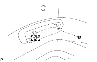
Engage the guide.
-
Install the reflex reflector assembly LH with the screw.
-
-
INSTALL REFLEX REFLECTOR ASSEMBLY RH
Tech Tips
Use the same procedure as for the LH side.
-
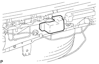
INSTALL NO. 2 LUGGAGE ROOM WIRE
-
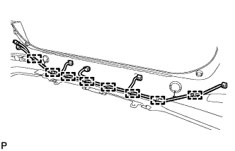
Engage the 8 clamps to install the No. 2 luggage room wire.
-
-
INSTALL REAR BUMPER UPPER COVER LH
-
Engage the 4 claws to install the rear bumper upper cover LH.
-
-
INSTALL REAR BUMPER UPPER COVER RH
Tech Tips
Use the same procedure as for the LH side.
-
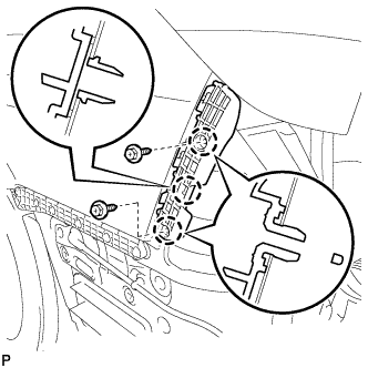
INSTALL NO. 3 REAR BUMPER SIDE RETAINER
-
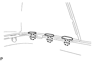
Engage the 3 claws to install the 3 No. 3 rear bumper side retainers.
Tech Tips
Use the same procedure for the RH side and LH side.
-
-
INSTALL REAR FOG LIGHT ASSEMBLY (w/ Rear Fog Light)
-
Install the rear fog light assembly and rear fog light bracket with the 2 screws.
-
-
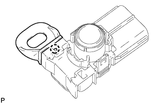
INSTALL NO. 2 ULTRASONIC SENSOR BEZEL (for Corner Sensor)
-
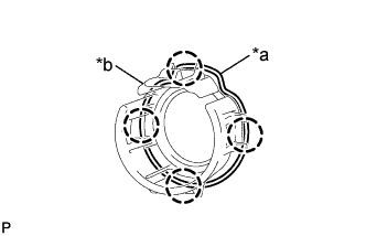
Text in Illustration *a Keyhole *b Slit Engage the 4 claws and install the No. 2 ultrasonic sensor bezel to the rear bumper assembly.
Tech Tips
-
When installing the retainer, align the keyhole and slit as shown in the illustration.
-
The illustration is for the RH side. The orientation for the LH side is the opposite of the RH side.
-
-
-
INSTALL NO. 1 ULTRASONIC SENSOR (for Corner Sensor)
-
for LH side:
-
Engage the claw to install the ultrasonic sensor clip to the No. 1 ultrasonic sensor assembly.
-
-
Engage the 2 claws to install the No. 1 ultrasonic sensor to the No. 2 ultrasonic sensor bezel.
Tech Tips
The orientation for the LH side is the opposite of the RH side.
-
Connect the connector.
-
for LH side:
-
Engage the clamp.
-
-
-
INSTALL NO. 3 ULTRASONIC SENSOR BEZEL (for Back Sensor)
-
for LH Side: Click here
-
for RH Side:
Tech Tips
Use the same procedure as for the LH side.
-
-
INSTALL NO. 1 ULTRASONIC SENSOR (for Back Sensor)
-
for LH Side: Click here
-
for RH Side:
Tech Tips
Use the same procedure as for the LH side.
-