FRONT BUMPER (for ALPHARD) REASSEMBLY

-
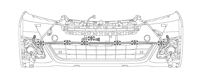
INSTALL FRONT BUMPER SIDE SUPPORT LH
-
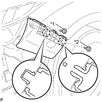
Text in Illustration *1 Bolt *2 Screw Engage the 2 claws.
-
Install the front bumper side support LH with the bolt and screw.
- Torque:
- Bolt
- 5.4 N*m { 55 kgf*cm, 48 in.*lbf }
-
-
INSTALL FRONT BUMPER SIDE SUPPORT RH
Tech Tips
Use the same procedure as for the LH side.
-
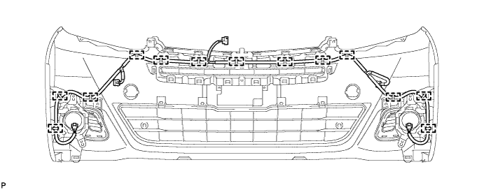
INSTALL FRONT BUMPER REINFORCEMENT SUB-ASSEMBLY
-
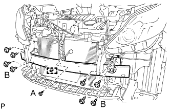
Install the front bumper reinforcement sub-assembly with the 9 bolts.
- Torque:
- Bolt A
- 8.5 N*m { 87 kgf*cm, 75 in.*lbf }
- Bolt B
- 70 N*m { 714 kgf*cm, 52 ft.*lbf }
-
Engage the clamp to connect the ambient temperature sensor.
-
w/ Headlight Cleaner System:
-
Engage the 3 clamps to connect the No. 2 headlight cleaner washer hose.
-
-
-
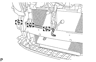
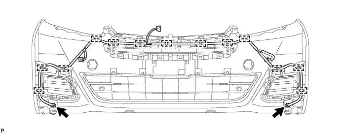
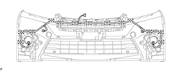
INSTALL FRONT BUMPER ENERGY ABSORBER
-
Engage the 4 guides to install the front bumper energy absorber.
-
-
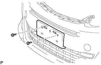
INSTALL FRONT BUMPER HOLE COVER
-
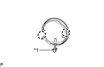
Text in Illustration *1 Hook Engage the hook.
-
Engage the 2 claws to install the front bumper hole cover to the front bumper cover.
Tech Tips
Use the same procedure for the RH side and LH side.
-
-
INSTALL FRONT BUMPER HOLE COVER LH (w/o Fog Light)
-
Engage the 2 guides and 5 claws.
-
Install the front bumper hole cover LH with the screw and 2 clips.
-
-
INSTALL FRONT BUMPER HOLE COVER RH (w/o Fog Light)
Tech Tips
Use the same procedure as for the LH side.
-
INSTALL FRONT BUMPER HOLE COVER ASSEMBLY LH (w/ Fog Light)
-
for Standard:
-
Engage the 2 guides and 5 claws.
-
Install the front bumper hole cover assembly LH with the screw and 2 clips.
-
-
for Sport Package:
-
Engage the 2 guides and 4 claws.
-
Install the front bumper hole cover assembly LH with the screw and 2 clips.
-
-
-
INSTALL FRONT BUMPER HOLE COVER ASSEMBLY RH (w/ Fog Light)
Tech Tips
Use the same procedure as for the LH side.
-
INSTALL LOWER NO. 1 RADIATOR GRILLE (for Standard)
-
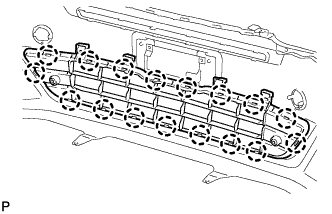
Engage the 17 claws to install the lower radiator grille.
-
-
INSTALL LOWER NO. 1 RADIATOR GRILLE (for Sport Package)
-
Engage the 18 claws to install the lower radiator grille.
-
-
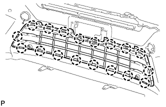
INSTALL INNER RADIATOR GRILLE
-
Engage the 12 claws to install the inner radiator grille.
-
-
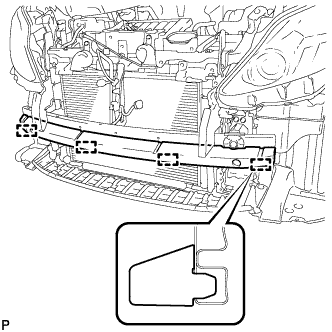
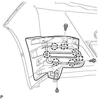
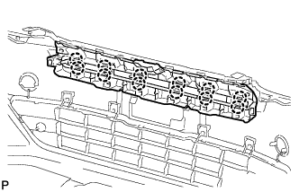
INSTALL NO. 4 ENGINE ROOM WIRE (for Standard)
-
w/o Fog Light:
-
Engage the 13 clamps to install the No. 4 engine room wire.
-
Connect the 2 connectors.
-
-
w/ Fog Light:
-
Engage the 13 clamps to install the No. 4 engine room wire.
-
-
-
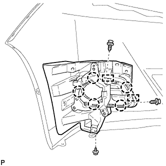
INSTALL NO. 4 ENGINE ROOM WIRE (for Sport Package)
-
Engage the 13 clamps to install the No. 4 engine room wire.
-
-
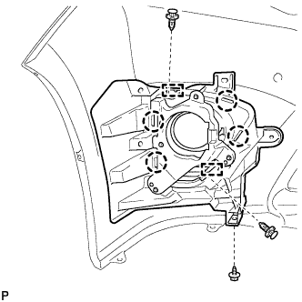
INSTALL NO. 1 HEADLIGHT CLEANER WASHER HOSE (w/ Headlight Cleaner System)
-
Engage the 7 clamps to install the No. 1 headlight cleaner washer hose.
-
-
INSTALL FRONT BUMPER EXTENTION MOUNTING BRACKET (w/ Bracket)
-
Install the front bumper extention mounting bracket with the 2 screws.
-
-
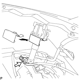
INSTALL HEADLIGHT WASHER ACTUATOR SUB-ASSEMBLY LH (w/ Headlight Cleaner System)
-
Engage the guide.
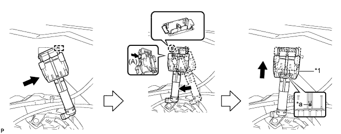
-
Push the tab shown by the arrow (A) and engage the claw as shown in the illustration.
-
Push up the headlight cleaner actuator clamp.
Note
Slide the headlight cleaner actuator clamp so that the pin is positioned as shown in the illustration.
-
Text in Illustration *1 Headlight Cleaner Actuator Clamp - - *a Pin - - Install the headlight washer actuator sub-assembly with the headlight cleaner clamp as shown in the illustration.
-
Connect the headlight cleaner hose.
-
-
INSTALL HEADLIGHT WASHER ACTUATOR SUB-ASSEMBLY RH (w/ Headlight Cleaner System)
Tech Tips
Use the same procedure as for the LH side.
-
INSTALL HEADLIGHT WASHER COVER LH (w/ Headlight Cleaner System)
-
Extend the headlight washer actuator sub-assembly.
-
Engage the 2 claws.
-
Engage the guide to install the headlight washer cover.
-
-
INSTALL HEADLIGHT WASHER COVER RH (w/ Headlight Cleaner System)
Tech Tips
Use the same procedure as for the LH side.
-
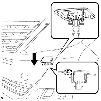
INSTALL FOG LIGHT ASSEMBLY LH (w/ Fog Light)
-
Engage the 3 guides.
-
Install the fog light assembly with the screw.
-
Connect the connector.
-
-
INSTALL FOG LIGHT ASSEMBLY RH (w/ Fog Light)
Tech Tips
Use the same procedure as for the LH side.
-
INSTALL NO. 1 ULTRASONIC SENSOR BEZEL (for RH Side)
-
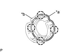
Text in Illustration *a Keyhole *b Slit Engage the 4 claws and install the No. 1 ultrasonic sensor bezel to the front bumper assembly.
Tech Tips
When installing the retainer, align the keyhole and slit as shown in the illustration.
-
-
INSTALL NO. 1 ULTRASONIC SENSOR BEZEL (for LH Side)
Tech Tips
Use the same procedure as for the RH side.
-
INSTALL NO. 1 ULTRASONIC SENSOR (for RH Side)
-
Engage the 2 claws to install the No. 1 ultrasonic sensor to the No. 1 ultrasonic sensor bezel.
-
Connect the connector.
-
-
INSTALL NO. 1 ULTRASONIC SENSOR (for LH Side)
Tech Tips
Use the same procedure as for the RH side.