AFS OFF SWITCH INSTALLATION

-
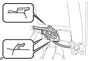
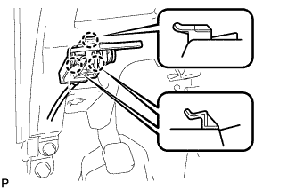
INSTALL AFS MAIN SWITCH (for RHD)
-
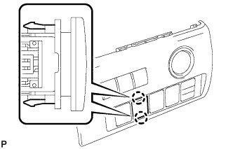
Engage the 2 claws to install the AFS main switch.
-
-
INSTALL AFS MAIN SWITCH (for LHD)
-
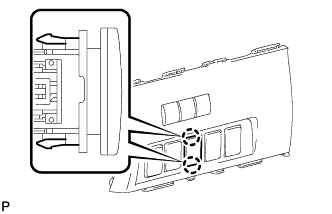
Engage the 2 claws to install the AFS main switch.
-
-
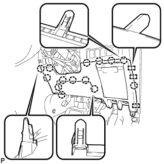
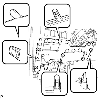
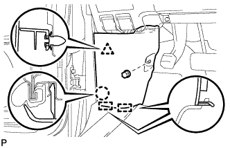
INSTALL NO. 1 SWITCH HOLE BASE
-
Connect each connector.
-
Engage the 6 claws and 3 guides to install the No. 1 switch hole base.
-
-
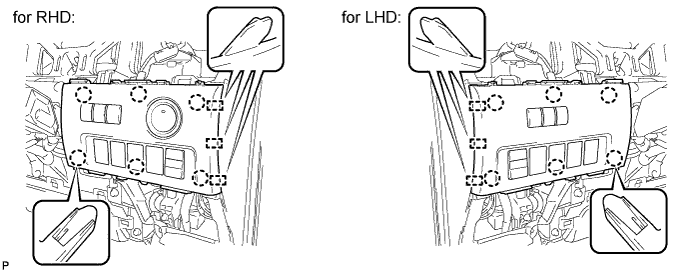
INSTALL LOWER INSTRUMENT PANEL FINISH PANEL (for RHD)
-
Engage the 3 guides and 14 claws.
Tech Tips
Make sure that all claws around the entire circumference of the driver side knee airbag assembly are fully engaged.
Note
Make sure that the claws are fully engaged.
-
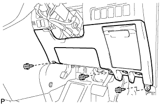
Install the lower instrument panel finish panel with the 3 screws <B>.
-

Engage the 3 claws and the fuel lid lock control cable assembly.
-
Engage the 3 claws and the hood lock control cable assembly.
-
-
INSTALL LOWER INSTRUMENT PANEL FINISH PANEL (for LHD)
-
Engage the 3 guides, 13 claws and clip.
Tech Tips
Make sure that all claws around the entire circumference of the driver side knee airbag assembly are fully engaged.
Note
Make sure that the claws are fully engaged.
-
Install the lower instrument panel finish panel with the 3 screws <B>.
-

Connect the fuel filler opening lid lock sub-assembly to the fuel lid lock open lever sub-assembly.
-
Engage the 3 claws and the fuel lid lock control cable assembly.
-

Engage the 3 claws and the hood lock control cable assembly.
-
-
INSTALL COWL SIDE TRIM BOARD RH (for RHD)
-

Engage the 2 guides, claw and clip to install the cowl side trim board RH.
-
Install the clip(A).
-
-
INSTALL COWL SIDE TRIM BOARD LH (for LHD)
-
Engage the 2 guides, claw and clip to install the cowl side trim board LH.
-
Install the clip(A).
-
-
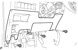
INSTALL NO. 1 INSTRUMENT PANEL UNDER COVER SUB-ASSEMBLY (for RHD)
-
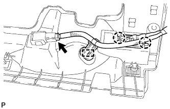
Engage the 2 claws and DLC3.
-
Engage the clamp.
-
Connect the connector.
-

Engage the 2 claws and 2 guides.
Note
Make sure that the claws are fully engaged.
-
Install the No. 1 instrument panel under cover sub-assembly with the 2 screws <B>.
-
-
INSTALL NO. 1 INSTRUMENT PANEL UNDER COVER SUB-ASSEMBLY (for LHD)
-
Engage the clamp.
-
Connect each connector.
-

Engage the 2 claws and guide.
Note
Make sure that the claws are fully engaged.
-
Install the No. 1 instrument panel under cover sub-assembly with the 2 screws <B>.
-
-
INSTALL NO. 1 INSTRUMENT CLUSTER FINISH PANEL GARNISH
-
Connect the connector.
-
Engage the 4 claws to install the No. 1 instrument cluster finish panel garnish.
-
-
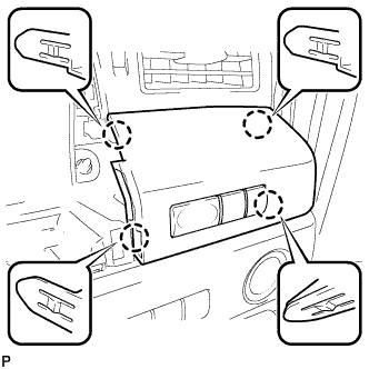
INSTALL NO. 1 INSTRUMENT CLUSTER FINISH PANEL
-
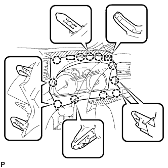
Engage the 11 claws and 2 guides to install the No. 1 instrument cluster finish panel.
-
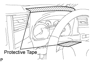
Remove the protective tape from the steering column cover.
-