LIGHTING SYSTEM AFS ECU Power Source Circuit
DESCRIPTION
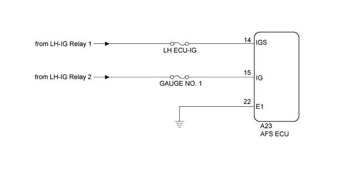
This circuit detects the state of the engine switch, and sends it to the AFS ECU.
WIRING DIAGRAM
INSPECTION PROCEDURE
PROCEDURE
-
CHECK HARNESS AND CONNECTOR (BATTERY - AFS ECU)
-
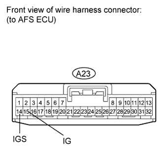
Disconnect the A23 AFS ECU connector.
-
Measure the voltage according to the value(s) in the table below.
Standard Voltage Tester Connection Switch Condition Specified Condition A23-14 (IGS) - Body ground Engine switch on (IG) 11 to 14 V Engine switch off Below 1 V A23-15 (IG) - Body ground Engine switch on (IG) 11 to 14 V Engine switch off Below 1 V
NG 
REPAIR OR REPLACE HARNESS OR CONNECTOR
OK 
-
-
CHECK HARNESS AND CONNECTOR (AFS ECU - BODY GROUND)
-
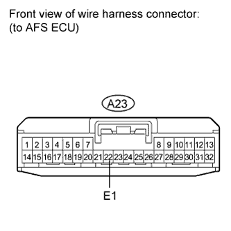
Measure the resistance according to the value(s) in the table below.
Standard Resistance Tester Connection Condition Specified Condition A23-22 (E1) - Body ground Always Below 1 Ω
NG
REPAIR OR REPLACE HARNESS OR CONNECTOR
OK 
PROCEED TO NEXT SUSPECTED AREA SHOWN IN PROBLEM SYMPTOMS TABLE Click here
-