LIGHTING SYSTEM Headlight Beam Level Control Actuator Circuit
DESCRIPTION
The headlight leveling ECU assembly actuates the headlight leveling motor according to vehicle conditions.
WIRING DIAGRAM
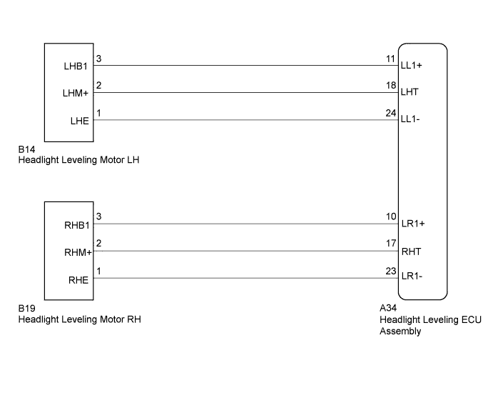
INSPECTION PROCEDURE
PROCEDURE
-
CHECK HARNESS AND CONNECTOR (HEADLIGHT LEVELING MOTOR - HEADLIGHT LEVELING ECU ASSEMBLY)
-
Disconnect the A34 headlight leveling ECU connector.
-
Disconnect the B14 or B19 headlight leveling motor connector.
-
Measure the resistance according to the value(s) in the table below.
Standard Resistance LH Side Tester Connection Condition Specified Condition A34-18 (LHT) - B14-2 (LHM+) Always Below 1 Ω A34-11 (LL1+) - B14-3 (LHB1) Always Below 1 Ω A34-24 (LL1-) - B14-1 (LHE) Always Below 1 Ω A34-18 (LHT) - Body ground Always 10 kΩ or higher A34-11 (LL1+) - Body ground Always 10 kΩ or higher A34-24 (LL1-) - Body ground Always 10 kΩ or higher RH Side Tester Connection Condition Specified Condition A34-17 (RHT) - B19-2 (RHM+) Always Below 1 Ω A34-10 (LR1+) - B19-3 (RHB1) Always Below 1 Ω A34-23 (LR1-) - B19-1 (RHE) Always Below 1 Ω A34-17 (RHT) - Body ground Always 10 kΩ or higher A34-10 (LR1+) - Body ground Always 10 kΩ or higher A34-23 (LR1-) - Body ground Always 10 kΩ or higher
NG 
REPAIR OR REPLACE HARNESS OR CONNECTOR
OK 
PROCEED TO NEXT SUSPECTED AREA SHOWN IN PROBLEM SYMPTOMS TABLE Click here
-