LIGHTING SYSTEM, Diagnostic DTC:B1244

| DTC Code | DTC Name |
|---|---|
| B1244 | Light Sensor Circuit Malfunction |
DESCRIPTION
The automatic light control sensor detects ambient light, converts it into an electrical signal, and outputs it to the main body ECU. The main body ECU turns on or off the headlights and taillights according to the signal.
| DTC No. | DTC Detection Condition | Trouble Area |
|---|---|---|
| B1244 |
|
|
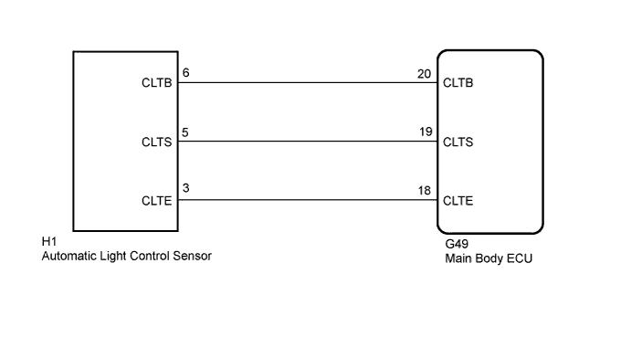
WIRING DIAGRAM
INSPECTION PROCEDURE
PROCEDURE
-
CHECK HARNESS AND CONNECTOR (MAIN BODY ECU - AUTOMATIC LIGHT CONTROL SENSOR)
-
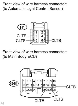
Disconnect the H1 automatic light control sensor connector.
-
Disconnect the G49 main body ECU connector.
-
Measure the resistance according to the value(s) in the table below.
Standard Resistance Tester Connection Condition Specified Condition G49-18 (CLTE) - H1-3 (CLTE) Always Below 1 Ω G49-18 (CLTE) - Body ground Always 10 kΩ or higher G49-19 (CLTS) - H1-5 (CLTS) Always Below 1 Ω G49-19 (CLTS) - Body ground Always 10 kΩ or higher G49-20 (CLTB) - H1-6 (CLTB) Always Below 1 Ω G49-20 (CLTB) - Body ground Always 10 kΩ or higher
NG 
REPAIR OR REPLACE HARNESS OR CONNECTOR
OK 
-
-
INSPECT MAIN BODY ECU
-
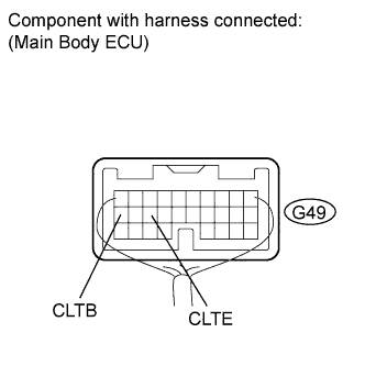
Reconnect the main body ECU connector.
-
Measure the voltage and resistance according to the value(s) in the table below.
Standard Voltage Tester Connection Condition Specified Condition G49-20 (CLTB) - G49-18 (CLTE) Engine switch off Below 1 V Engine switch on (IG) 11 to 14 V Standard Resistance Tester Connection Condition Specified Condition G49-18 (CLTE) - Body ground Always Below 1 Ω
NG
REPLACE MAIN BODY ECU Click here
OK
-
-
INSPECT AUTOMATIC LIGHT CONTROL SENSOR
-
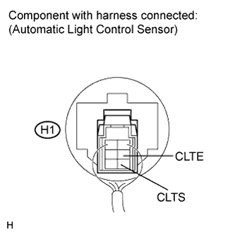
Reconnect the automatic light control sensor connector.
-
Connect an oscilloscope to the automatic light control sensor connector.
-
Check the waveform.
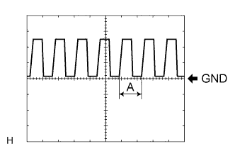
OK Tester Connection Tool Setting Condition Specified Condition H1-3 (CLTE) - H1-5 (CLTS) 5 V/DIV., 5 ms./DIV. Engine switch on (IG), light control switch in AUTO Correct waveform is as shown Tech Tips
If the ambient light becomes brighter, width A becomes narrower.
NG
REPLACE AUTOMATIC LIGHT CONTROL SENSOR Click here
OK 
REPLACE MAIN BODY ECU Click here
-