LIGHTING SYSTEM TERMINALS OF ECU

-
CHECK MAIN BODY ECU
-
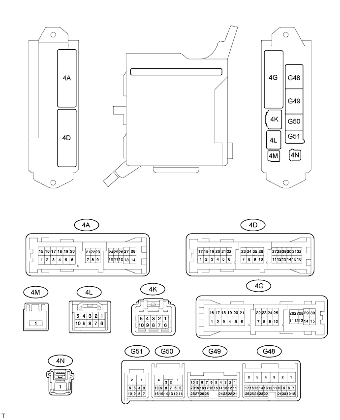
Disconnect the G49, G50, 4A, 4D and 4K ECU connectors.
-
Measure the resistance and voltage according to the value(s) in the table below.
Standard Resistance Terminal No. (Symbol) Wiring Color Terminal Description Condition Specified Condition G50-1 (GND) - Body ground W-B - Body ground Ground Always Below 1 Ω 4A-3 (GND2) - Body ground W-B - Body ground Ground Always Below 1 Ω Standard Voltage Terminal No. (Symbol) Wiring Color Terminal Description Condition Specified Condition 4A-26 (ACC) - Body ground GR - Body ground ACC power supply Engine switch on (ACC) 11 to 14 V Engine switch off Below 1 V 4K-9 (BATB) - Body ground W - Body ground Battery power supply Always 11 to 14 V
-
If the result is not as specified, there may be a malfunction in the wire harness side.
-
-
Reconnect the G49, G50, 4A, 4D and 4K ECU connectors.
-
Measure the resistance and voltage according to the value(s) in the table below.
Standard Resistance Terminal No. (Symbol) Wiring Color Terminal Description Condition Specified Condition G49-18 (CLTE) - Body ground LG - Body ground Automatic light control sensor ground Always Below 1 Ω Standard Voltage Terminal No. (Symbol) Wiring Color Terminal Description Condition Specified Condition G48-4 (FFGO) - Body ground LG - Body ground Front fog light relay drive output Front fog light switch off 11 to 14 V Light control switch in TAIL or HEAD, front fog light switch on Below 1 V G48-13 (HF) - Body ground Y - Body ground Dimmer switch HIGH FLASH signal input Dimmer switch not in HIGH FLASH 11 to 14 V Dimmer switch in HIGH FLASH Below 1 V G48-21 (A) - Body ground V - Body ground Light control switch AUTO signal input Light control switch not in AUTO Pulse generation Light control switch in AUTO Below 1 V G48-23 (TAIL) - Body ground G - Body ground Light control switch TAIL signal input Light control switch off and engine switch off Pulse generation Light control switch off and engine switch on (IG) 11 to 14 V Light control switch in TAIL Below 1 V G48-24 (DCTY) - Body ground W - Body ground Driver side door courtesy switch input Driver side door closed Pulse generation Driver side door open Below 1 V G49-7 (RCTY) - Body ground LG - Body ground Slide door RH courtesy light switch input Slide door RH closed Pulse generation Slide door RH open Below 1 V G49-9 (RFOG) - Body ground L - Body ground Rear fog light switch input Rear fog light switch on Below 1 V Rear fog light switch off 11 to 14 V G49-17 (HEAD) - Body ground W - Body ground Light control switch HEAD signal input Light control switch off and engine switch off Pulse generation Light control switch in HEAD and engine switch on (IG) 11 to 14 V Light control switch in HEAD Below 1 V G49-19 (CLTS) - Body ground B - Body ground Automatic light control sensor signal input Engine switch on (IG), light control switch in AUTO Pulse generation
(See waveform 1)
Engine switch off Below 1 V G49-20 (CLTB) - Body ground GR - Body ground Automatic light control sensor power supply output Engine switch on (IG) 11 to 14 V Engine switch off Below 1 V G49-21 (PCTY) - Body ground L - Body ground Front passenger side door courtesy switch input Front passenger side door closed 11 to 14 V Front passenger side door open Below 1 V G49-28 (FFOG) - Body ground LG - Body ground Front fog light switch input Front fog light switch off Pulse generation Light control switch in TAIL or HEAD, front fog light switch on Below 1 V G50-5 (CANH) - Body ground G - Body ground CAN communication Engine switch off Below 1 V Engine switch on (IG) Pulse generation G50-6 (CANL) - Body ground W - Body ground CAN communication Engine switch off Below 1 V Engine switch on (IG) Pulse generation G50-15 (CANN) - Body ground W - Body ground CAN communication Engine switch off Below 1 V Engine switch on (IG) Pulse generation G50-16 (CANP) - Body ground B - Body ground CAN communication Engine switch off Below 1 V Engine switch on (IG) Pulse generation G50-14 (RFGO) - Body ground LG- Body ground Rear fog light relay drive output Taillights on and rear fog light switch on Below 1 V Rear fog light switch off 11 to 14 V 4A-4 (LCTY) - Body ground R- Body ground Slide door LH courtesy switch input Slide door LH closed Pulse generation Slide door LH open Below 1 V 4D-10 (HU) - Body ground P - Body ground Dimmer switch HIGH signal input Dimmer switch in LOW Pulse generation Dimmer switch in HIGH Below 1 V 4K-8 (DRL) - Body ground B - Body ground Headlight dimmer relay drive output Dimmer switch in LOW 11 to 14 V Light control switch in HEAD, dimmer switch in HIGH or HIGH FLASH Below 1 V 4L-6 (HRLY) - Body ground BR - Body ground Headlight relay drive output Light control switch off 11 to 14 V Light control switch in HEAD Below 1 V
-
If the result is not as specified, the ECU may have a malfunction.
-
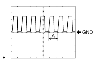
Waveform 1
Item Contents Tool setting 5 V/DIV., 5 ms./DIV. Tech Tips
If the ambient light becomes brighter, width A becomes narrower.
-
-
-
CHECK AFS ECU
-
Disconnect the A23 ECU connector.

-
Measure the resistance and voltage according to the value(s) in the table below.
Standard Resistance Terminal No. (Symbol) Wiring Color Terminal Description Condition Specified Condition A23-22 (E1) - Body ground W-B - Body ground AFS ECU ground Always Below 1 Ω Standard Voltage Terminal No. (Symbol) Wiring Color Terminal Description Condition Specified Condition A23-14 (IGS) - Body ground P - Body ground Swivel motor power supply Engine switch off Below 1 V Engine switch on (IG) 11 to 14 V A23-15 (IG) - Body ground W - Body ground AFS ECU power supply Engine switch off Below 1 V Engine switch on (IG) 11 to 14 V If the result is not as specified, there may be a malfunction on the wire harness side.
-
Reconnect the A23 ECU connector.
-
Measure the resistance and voltage according to the value(s) in the table below.
Standard Resistance Terminal No. (Symbol) Wiring Color Terminal Description Condition Specified Condition A23-21 (SGF) - A23-22 (E1) BE - W-B Rear height control sensor ground Always Below 1 Ω A23-23 (SMGL) - A23-22 (E1) GR - W-B Swivel motor LH ground Always Below 1 Ω A23-24 (SMGR) - A23-22 (E1) B - W-B Swivel motor RH ground Always Below 1 Ω A23-27 (LL1-) - A23-22 (E1) W - W-B Leveling motor LH ground Always Below 1 Ω A23-28 (LR1-) - A23-22 (E1) BE - W-B Leveling motor RH ground Always Below 1 Ω Standard Voltage Terminal No. (Symbol) Wiring Color Terminal Description Condition Specified Condition A23-1 (SMBL) - A23-22 (E1) SB - W-B Swivel motor LH power supply Engine switch off Below 1 V Engine switch on (IG) 11 to 16 V A23-2 (SMBR) - A23-22 (E1) LG - W-B Swivel motor RH power supply Engine switch off Below 1 V Engine switch on (IG) 11 to 16 V A23-3 (LL1+) - A23-22 (E1) Y - W-B Leveling motor LH power supply Engine switch off Below 1 V Engine switch on (IG) 11 to 16 V A23-4 (LR1+) - A23-22 (E1) R - W-B Leveling motor RH power supply Engine switch off Below 1 V Engine switch on (IG) 11 to 16 V A23-7 (INIT) - A23-22 (E1) BR - W-B Initialization signal Engine switch on (IG), terminal LVL and GND of DLC3 connected Below 1 V Engine switch on (IG), terminal LVL and GND of DLC3 not connected Approx. 5 V A23-10 (SMR) - A23-22 (E1) L - W-B Swivel motor RH LIN communication Engine switch off Below 1 V Engine switch on (IG) Pulse generation A23-11 (RHT) - A23-22 (E1) P - W-B Leveling motor RH LIN communication Engine switch off Below 1 V Engine switch on (IG) Pulse generation A23-12 (CANH) - A23-22 (E1) B - W-B CAN communication Engine switch off Below 1 V Engine switch on (IG) Pulse generation A23-13 (CANL) - A23-22 (E1) W - W-B CAN communication Engine switch off Below 1 V Engine switch on (IG) Pulse generation A23-18 (B) - A23-21 (SGF) V - BE Rear height control sensor power supply Engine switch off Below 1 V Engine switch on (IG) Approx. 5 V A23-19 (SHRL) - A23-21 (SGF) Y - BE Rear height control sensor signal Engine switch off Below 1 V Engine switch on (IG) 1 V to 4 V A23-29 (SML) - A23-22 (E1) G - W-B Swivel motor LH LIN communication Engine switch off Below 1 V Engine switch on (IG) Pulse generation A23-30 (LHT) - A23-22 (E1) V - W-B Leveling motor LH LIN communication Engine switch off Below 1 V Engine switch on (IG) Pulse generation A23-32 (MSW) - A23-22 (E1) G - W-B AFS OFF switch signal Engine switch on (IG), AFS OFF switch off (not pushed) 11 to 16 V Engine switch on (IG), AFS OFF switch on (pushed) Below 1 V If the result is not as specified, the ECU may have a malfunction.
-
-
CHECK HEADLIGHT LEVELING ECU ASSEMBLY
-
Disconnect the A34 headlight leveling ECU assembly connector.

-
Measure the voltage and resistance between the specified terminals of the wire harness side connectors and body ground.
Standard Voltage Terminal No. (Symbol) Wiring Color Terminal Description Condition Specified Condition A34-1 (IG) - Body ground W - Body ground IG power supply Engine switch off Below 1 V Engine switch on (IG) 11 to 14 V Standard Resistance Terminal No. (Symbol) Wiring Color Terminal Description Condition Specified Condition A34-9 (E1) - Body ground W-B - Body ground Ground Always Below 1 Ω If the result is not as specified, there may be a malfunction on the wire harness side.
-
Reconnect the A34 headlight leveling ECU assembly connector.
-
Measure the resistance and voltage according to the value(s) in the table below.
Standard Resistance Terminal No. (Symbol) Wiring Color Terminal Description Condition Specified Condition A34-21 (SGR) - Body ground L - Body ground Rear height control sensor ground Always Below 1 Ω A34-23 (LR1-) - Body ground BE - Body ground Leveling motor RH ground Always Below 1 Ω A34-24 (LL1-) - Body ground W - Body ground Leveling motor LH ground Always Below 1 Ω Standard Voltage Terminal No. (Symbol) Wiring Color Terminal Description Condition Specified Condition A34-3 (HDLP) - Body ground B - Body ground Low beam headlight signal input Low beam headlights on Below 1.5 V Low beam headlights off Above 5 V A34-5 (PRST) - Body ground BR - Body ground Initialization signal input Terminal LVL and terminal GND of DLC3 connected Below 1 V Terminal LVL and terminal GND of DLC3 not connected Approx. 5 V A34-6 (WNG) - Body ground P - Body ground Indicator light drive output Indicator light on 11 to 14 V Indicator light off Below 1 V A34-10 (LR1+) - Body ground R - Body ground Leveling motor RH power supply Engine switch off Below 1 V Engine switch on (IG) 10 to 16 V A34-11 (LL1+) - Body ground Y - Body ground Leveling motor LH power supply Engine switch off Below 1 V Engine switch on (IG) 10 to 16 V A34-12 (SBR) - Body ground BE - Body ground Rear height control sensor power supply Engine switch off Below 1 V Engine switch on (IG) 4.75 to 5.25 V A34-16 (SPD) - Body ground GR - Body ground Vehicle speed signal input Vehicle is driven at approx. 20 km/h (12mph) Pulse generation
(See waveform 1)
A34-17 (RHT) - Body ground P - Body ground Leveling motor RH operation signal input With low beam headlights on, vehicle height not changed Below 1 V With low beam headlights on, change vehicle height and keep for more than 3 seconds. 1.0 to 14.4 V A34-18 (LHT) - Body ground V - Body ground Leveling motor LH operation signal input With low beam headlights on, vehicle height not changed Below 1 V With low beam headlights on, change vehicle height and keep for more than 3 seconds. 1.0 to 14.4 V A34-19 (SHRL) - Body ground Y - Body ground Rear height control sensor signal input Engine switch off Below 1 V Engine switch on (IG) 0.5 to 4.5 V If the result is not as specified, the headlight leveling ECU assembly may have a malfunction.
-
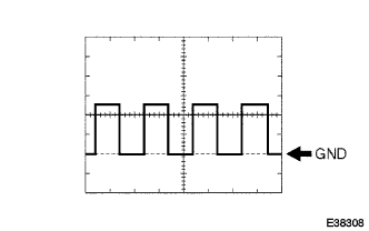
Waveform 1
Item Content Tool setting 2 V/DIV., 2 ms./DIV.
-
-
-
CHECK INNER REAR VIEW MIRROR ASSEMBLY (w/ Automatic High Beam System)
-
Disconnect the R33 inner rear view mirror assembly connector.

-
Measure the resistance according to the value(s) in the table below.
Terminal No. (Symbol) Wiring Color Terminal Description Condition Specified Condition R33-2 (E) - Body ground W-B - Body ground Inner rear view mirror assembly ground Always Below 1 Ω If the result is not as specified, there may be a malfunction in the wire harness.
-
Measure the voltage according to the value(s) in the table below.
Terminal No. (Symbol) Wiring Color Terminal Description Condition Specified Condition R33-1 (IG) - Body ground Y - Body ground Inner rear view mirror assembly power supply Engine switch off Below 1 V Engine switch on (IG) 11 to 14 V If the result is not as specified, there may be a malfunction in the wire harness.
-
Reconnect the R33 inner rear view mirror assembly connector.
-
Measure the voltage or check for pulses according to the value(s) in the table below.
Terminal No. (Symbol) Wiring Color Terminal Description Condition Specified Condition R33-12 (LIN) - R33-2 (E) W - W-B LIN communication Engine switch off Below 1 V Automatic high beam system operates Pulse generation
(See waveform 1)
If the result is not as specified, the inner rear view mirror assembly may have a malfunction.
-
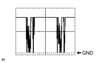
Waveform 1
Item Content Tool setting 2 V/DIV., 20 ms./DIV.
-
-