Click here
DESCRIPTION
This circuit detects the state of the engine switch, and sends it to the headlight leveling ECU assembly.
Click here
INSPECTION PROCEDURE
Note:
Inspect the fuses for circuits related to this system before performing the following inspection procedure.
Click here
PROCEDURE
- Click here
CHECK HARNESS AND CONNECTOR (BATTERY - HEADLIGHT LEVELING ECU ASSEMBLY)
-
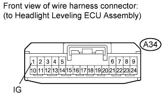
Disconnect the A34 headlight leveling ECU assembly connector.
-
Measure the voltage according to the value(s) in the table below.
Standard Voltage Tester Connection Switch Condition Specified Condition A34-1 (IG) - Body ground Engine switch on (IG) 11 to 14 V A34-1 (IG) - Body ground Engine switch off Below 1 V
- OKClick here
- NGClick here
-
- Click here
CHECK HARNESS AND CONNECTOR (HEADLIGHT LEVELING ECU ASSEMBLY - BODY GROUND)
-
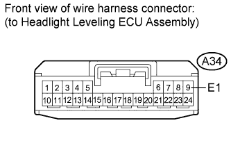
Measure the resistance according to the value(s) in the table below.
Standard Resistance Tester Connection Condition Specified Condition A34-9 (E1) - Body ground Always Below 1 Ω
- OKClick here
- NGClick here
-
- Click here
PROCEED TO NEXT SUSPECTED AREA SHOWN IN PROBLEM SYMPTOMS TABLEClick here
- Click here
REPAIR OR REPLACE HARNESS OR CONNECTOR