DESCRIPTION
The main body ECU receives the following signals:
-
Light control switch TAIL, HEAD or AUTO signal
-
Dimmer switch HIGH or FLASH (PASS) signal
-
Front fog light switch signal
When performing troubleshooting, inspect the switch that is related to the malfunction. For example, if both right and left low beam headlights do not illuminate, read the light control switch HEAD signal value only in the Data List. If the value is normal, perform the headlight relay Active Test.
INSPECTION PROCEDURE
PROCEDURE
- Click here
READ VALUE USING INTELLIGENT TESTER
-
Connect the intelligent tester to the DLC3.
-
Turn the engine switch on (IG).
-
Turn the intelligent tester on.
-
Enter the following menus: Body / Main Body / Data List.
-
Read the displays on the intelligent tester.
Table 1. Main Body Tester Display Measurement Item/Range Normal Condition Diagnostic Note Dimmer Hi SW Dimmer switch HIGH signal / ON or OFF ON: Dimmer switch in HIGH
OFF: Dimmer switch in LOW
- Passing Light SW Dimmer switch FLASH signal / ON or OFF ON: Dimmer switch in HIGH FLASH (PASS)
OFF: Dimmer switch not in HIGH FLASH (PASS)
- Rear Fog Light SW Rear fog light switch signal / ON or OFF ON: Rear fog light switch on
OFF: Rear fog light switch off
- Front Fog Light SW Front fog light switch signal / ON or OFF ON: Front fog light switch on
OFF: Front fog light switch off
- Light Auto SW Light control switch AUTO signal / ON or OFF ON: Light control switch in AUTO
OFF: Light control switch not in AUTO
- Headlight SW Light control switch HEAD signal / ON or OFF ON: Light control switch in HEAD
OFF: Light control switch not in HEAD
- Taillight SW Light control switch TAIL signal / ON or OFF ON: Light control switch in TAIL or HEAD
OFF: Light control switch in neither TAIL nor HEAD
- OK Normal conditions listed above are displayed.
- OKClick here
- NGClick here
-
- Click here
INSPECT HEADLIGHT DIMMER SWITCH ASSEMBLY
-
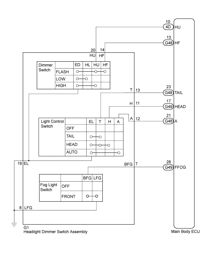
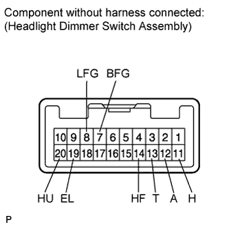
for RHD
-
Remove the headlight dimmer switch assembly (Click here).
-
Measure the resistance according to the value(s) in the table below.
Standard Resistance Light Control Switch Tester Connection Switch Condition Specified Condition 19 (EL) - 13 (T) off 10 kΩ or higher 13 (T) - 12 (A) 12 (A) - 11 (H) 19 (EL) - 13 (T) TAIL Below 1 Ω 19 (EL) - 13 (T) HEAD Below 1 Ω 13 (T) - 11 (H) 19 (EL) - 12 (A) AUTO Below 1 Ω Dimmer Switch Tester Connection Switch Condition Specified Condition 20 (HU) - 19 (EL) HIGH Below 1 Ω 19 (EL) - 20 (HU) HIGH FLASH Below 1 Ω 19 (EL) - 14 (HF) Below 1 Ω Front Fog Light Switch Tester Connection Switch Condition Specified Condition 8 (LFG) - 7 (BFG) off 10 kΩ or higher on Below 1 Ω
-
-
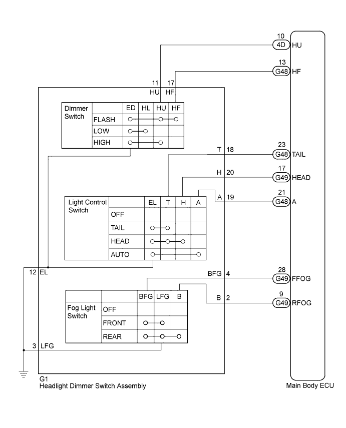
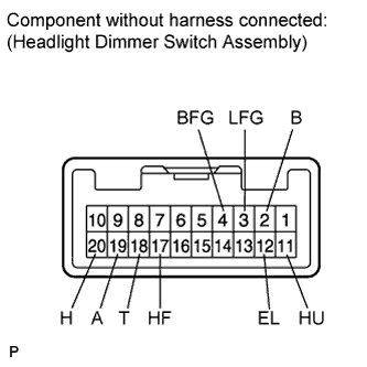
for LHD
-
Remove the headlight dimmer switch assembly (Click here).
-
Measure the resistance according to the value(s) in the table below.
Standard Resistance Light Control Switch Tester Connection Switch Condition Specified Condition 12 (EL) - 18 (T) off 10 kΩ or higher 18 (T) - 19 (A) 19 (A) - 20 (H) 12 (EL) - 18 (T) TAIL Below 1 Ω 12 (EL) - 18 (T) HEAD Below 1 Ω 18 (T) - 20 (H) 12 (EL) - 19 (A) AUTO Below 1 Ω Dimmer Switch Tester Connection Switch Condition Specified Condition 11 (HU) - 12 (EL) HIGH Below 1 Ω 12 (EL) - 11 (HU) HIGH FLASH Below 1 Ω 12 (EL) - 17 (HF) Below 1 Ω Front Fog Light Switch Tester Connection Switch Condition Specified Condition 3 (LFG) - 4 (BFG) off 10 kΩ or higher on Below 1 Ω Rear Fog Light Switch Tester Connection Switch Condition Specified Condition 2 (B) - 3 (LFG) off 10 kΩ or higher 2 (B) - 3 (LFG) - 4 (BFG) on Below 1 Ω
-
- OKClick here
- NGClick here
-
- Click here
CHECK HARNESS AND CONNECTOR (MAIN BODY ECU - HEADLIGHT DIMMER SWITCH ASSEMBLY)
-
for RHD
-
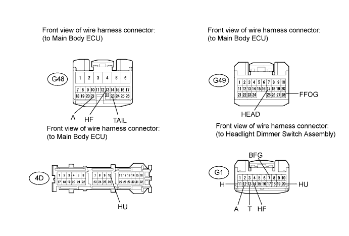
Disconnect the G1 headlight dimmer switch assembly connector.
-
Disconnect the G48, G49 and 4D main body ECU connectors.
-
Measure the resistance according to the value(s) in the table below.
Standard Resistance Tester Connection Condition Specified Condition G1-7 (BFG) - G49-28 (FFOG) Always Below 1 Ω G1-7 (BFG) - Body ground Always 10 kΩ or higher G1-11 (H) - G49-17 (HEAD) Always Below 1 Ω G1-11 (H) - Body ground Always 10 kΩ or higher G1-12 (A) - G48-21 (A) Always Below 1 Ω G1-12 (A) - Body ground Always 10 kΩ or higher G1-13 (T) - G48-23 (TAIL) Always Below 1 Ω G1-13 (T) - Body ground Always 10 kΩ or higher G1-14 (HF) - G48-13 (HF) Always Below 1 Ω G1-14 (HF) - Body ground Always 10 kΩ or higher G1-20 (HU) - 4D-10 (HU) Always Below 1 Ω G1-20 (HU) - Body ground Always 10 kΩ or higher
-
-
for LHD
-
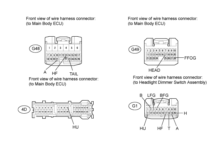
Disconnect the G1 headlight dimmer switch assembly connector.
-
Disconnect the G48, G49 and 4D main body ECU connectors.
-
Measure the resistance according to the value(s) in the table below.
Standard Resistance Tester Connection Condition Specified Condition G1-4 (BFG) - G49-28 (FFOG) Always Below 1 Ω G1-4 (BFG) - Body ground Always 10 kΩ or higher G1-20 (H) - G49-17 (HEAD) Always Below 1 Ω G1-20 (H) - Body ground Always 10 kΩ or higher G1-19 (A) - G48-21 (A) Always Below 1 Ω G1-19 (A) - Body ground Always 10 kΩ or higher G1-18 (T) - G48-23 (TAIL) Always Below 1 Ω G1-18 (T) - Body ground Always 10 kΩ or higher G1-17 (HF) - G48-13 (HF) Always Below 1 Ω G1-17 (HF) - Body ground Always 10 kΩ or higher G1-11 (HU) - 4D-10 (HU) Always Below 1 Ω G1-11 (HU) - Body ground Always 10 kΩ or higher G1-2 (B) - G49-9 (RFOG) Always Below 1 Ω G1-2 (B) - Body ground Always 10 kΩ or higher
-
- OKClick here
- NGClick here
-
- Click here
CHECK HARNESS AND CONNECTOR (HEADLIGHT DIMMER SWITCH ASSEMBLY - BODY GROUND)
-
for RHD
-
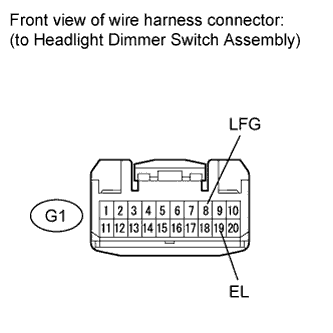
Measure the resistance according to the value(s) in the table below.
Standard Resistance Tester Connection Condition Specified Condition G1-8 (LFG) - Body ground Always Below 1 Ω G1-19 (EL) - Body ground Always Below 1 Ω
-
-
for LHD
-
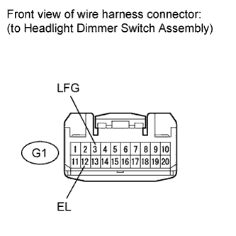
Measure the resistance according to the value(s) in the table below.
Standard Resistance Tester Connection Condition Specified Condition G1-3 (LFG) - Body ground Always Below 1 Ω G1-12 (EL) - Body ground Always Below 1 Ω
-
- OKClick here
- NGClick here
-
- Click here
PROCEED TO NEXT SUSPECTED AREA SHOWN IN PROBLEM SYMPTOMS TABLEClick here
- Click here
REPLACE HEADLIGHT DIMMER SWITCH ASSEMBLYClick here
- Click here
REPAIR OR REPLACE HARNESS OR CONNECTOR
- Click here
REPLACE MAIN BODY ECUClick here