LIGHTING SYSTEM Headlight (HI-BEAM) Circuit
DESCRIPTION
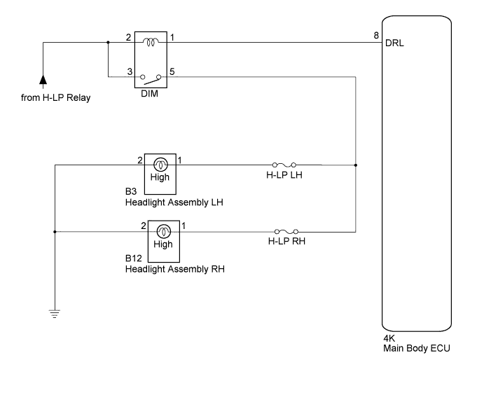
The main body ECU receives a signal from the headlight dimmer switch assembly to control the high beam headlights.
WIRING DIAGRAM
INSPECTION PROCEDURE
PROCEDURE
-
CHECK HEADLIGHT
-
Check the operation of the low beam headlights.
OK Low beam headlights operate normally.
NG 
GO TO PROBLEM SYMPTOMS TABLE Click here
OK 
-
-
PERFORM ACTIVE TEST USING INTELLIGENT TESTER
-
Connect the intelligent tester to the DLC3.
-
Turn the engine switch on (IG).
-
Turn the intelligent tester on.
-
Enter the following menus: Body / Main Body / Active Test.
-
Check the operation.
Main Body Tester Display Test Part Control Range Diagnostic Note Head Light (HI) Headlight dimmer relay ON/OFF - OK Relay operates. (High beam headlights illuminate.)
NG 
INSPECT HEADLIGHT DIMMER RELAY (DIM) Click here
OK 
PROCEED TO NEXT SUSPECTED AREA SHOWN IN PROBLEM SYMPTOMS TABLE Click here
-
-
INSPECT HEADLIGHT DIMMER RELAY (DIM)
-
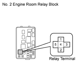
Remove the headlight dimmer relay from the No. 2 engine room relay block.
-
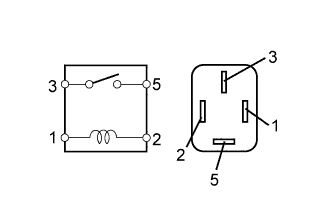
Measure the resistance according to the value(s) in the table below.
Standard Resistance Tester Connection Condition Specified Condition 3 - 5 Voltage is not applied between terminals 1 and 2 10 kΩ or higher 3 - 5 Voltage is applied between terminals 1 and 2 Below 1 Ω
NG
REPLACE HEADLIGHT DIMMER RELAY
OK
-
-
CHECK HARNESS AND CONNECTOR (H-LP RELAY - HEADLIGHT DIMMER RELAY)
-
Measure the voltage according to the value(s) in the table below.
Standard Voltage Tester Connection Switch Condition Specified Condition Headlight dimmer relay terminal 2 - Body ground Light control switch off → HEAD Below 1 V → 11 to 14 V Headlight dimmer relay terminal 3 - Body ground Light control switch off → HEAD Below 1 V → 11 to 14 V
NG
REPAIR OR REPLACE HARNESS OR CONNECTOR
OK
-
-
CHECK HARNESS AND CONNECTOR (HEADLIGHT DIMMER RELAY - MAIN BODY ECU)
-
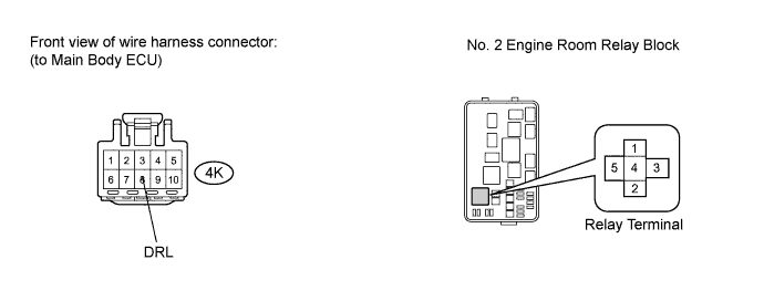
Disconnect the 4K main body ECU connector.
-
Measure the resistance according to the value(s) in the table below.
Standard Resistance Tester Connection Condition Specified Condition Headlight dimmer relay terminal 1 - 4K-8 (DRL) Always Below 1 Ω 4K-8 (DRL) - Body ground Always 10 kΩ or higher
NG
REPAIR OR REPLACE HARNESS OR CONNECTOR
OK
-
-
CHECK HARNESS AND CONNECTOR (HEADLIGHT ASSEMBLY - HEADLIGHT DIMMER RELAY AND BODY GROUND)
-
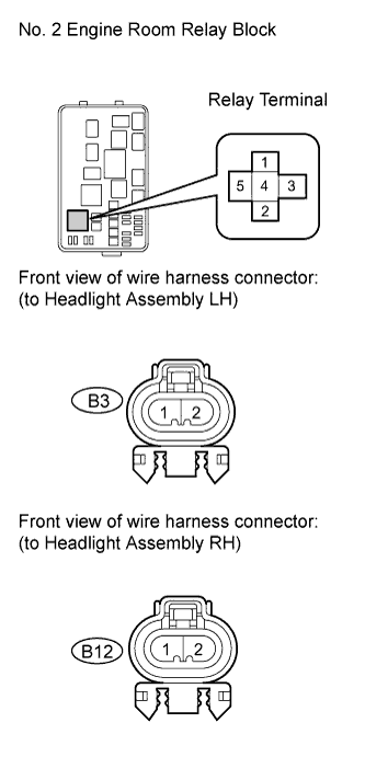
Disconnect the B3 and B12 headlight assembly connectors.
-
Measure the resistance according to the value(s) in the table below.
Standard Resistance Tester Connection Condition Specified Condition Headlight dimmer relay terminal 5 - B3-1 Always Below 1 Ω Headlight dimmer relay terminal 5 - B12-1 Always Below 1 Ω B3-1 - Body ground Always 10 kΩ or higher B12-1 - Body ground Always 10 kΩ or higher B3-2 - Body ground Always Below 1 Ω B12-2 - Body ground Always Below 1 Ω
NG
REPAIR OR REPLACE HARNESS OR CONNECTOR
OK
REPLACE MAIN BODY ECU Click here
-