LIGHTING SYSTEM Front Fog Light Circuit
DESCRIPTION
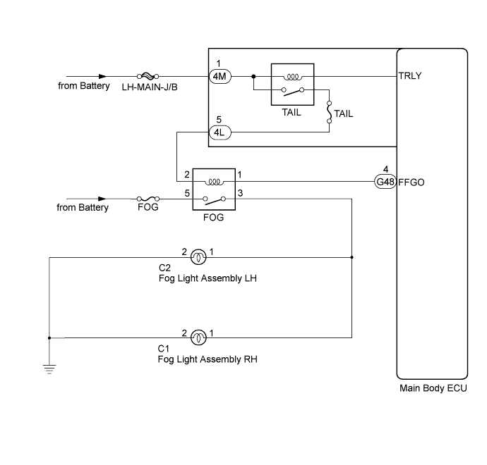
The main body ECU controls the front fog light relay when a signal is received from the headlight dimmer switch assembly.
WIRING DIAGRAM
INSPECTION PROCEDURE
PROCEDURE
-
PERFORM ACTIVE TEST USING INTELLIGENT TESTER
-
Connect the intelligent tester to the DLC3.
-
Turn the engine switch on (IG).
-
Turn the intelligent tester on.
-
Enter the following menus: Body / Main Body / Active Test.
-
Check the operation.
Main Body Tester Display Test Part Control Range Diagnostic Note Front Fog Light Relay Front fog light relay ON/OFF - OK Front fog relay operates. (Front fog lights come on.)
NG 
INSPECT FRONT FOG LIGHT RELAY (FOG) Click here
OK 
PROCEED TO NEXT SUSPECTED AREA SHOWN IN PROBLEM SYMPTOMS TABLE Click here
-
-
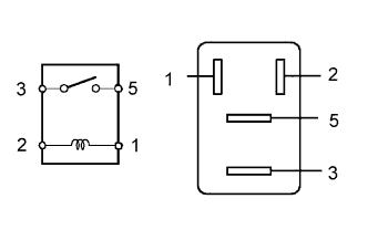
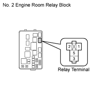
INSPECT FRONT FOG LIGHT RELAY (FOG)
-
Remove the front fog light relay from the No. 2 engine room junction block.
-
Measure the resistance according to the value(s) in the table below.
Standard Resistance Tester Connection Condition Specified Condition 3 - 5 Voltage is not applied between terminals 1 and 2 10 kΩ or higher 3 - 5 Voltage is applied between terminals 1 and 2 Below 1 Ω
NG 
REPLACE FRONT FOG LIGHT RELAY
OK 
-
-
CHECK HARNESS AND CONNECTOR (BATTERY - FRONT FOG LIGHT RELAY)
-
Measure the voltage according to the value(s) in the table below.
Standard Voltage Tester Connection Condition Specified Condition Front fog light relay terminal 5 - Body ground Always 11 to 14 V Front fog light relay terminal 2 - Body ground Light control switch off → TAIL Below 1 V → 11 to 14 V
NG
REPAIR OR REPLACE HARNESS OR CONNECTOR
OK
-
-
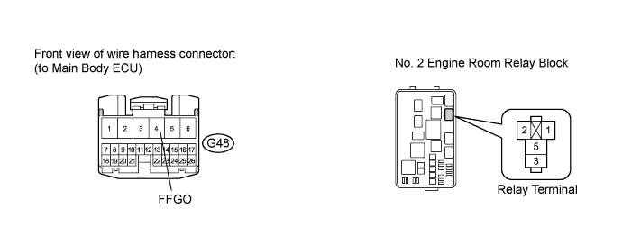
CHECK HARNESS AND CONNECTOR (FRONT FOG LIGHT RELAY - MAIN BODY ECU)
-
Disconnect the G48 main body ECU connector.
-
Measure the resistance according to the value(s) in the table below.
Standard Resistance Tester Connection Condition Specified Condition Front fog light relay terminal 1 - G48-4 (FFGO) Always Below 1 Ω G48-4 (FFGO) - Body ground Always 10 kΩ or higher
NG
REPAIR OR REPLACE HARNESS OR CONNECTOR
OK
-
-
CHECK HARNESS AND CONNECTOR (FOG LIGHT ASSEMBLY - FRONT FOG LIGHT RELAY AND BODY GROUND)
-
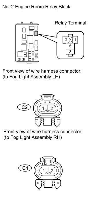
Disconnect the C1 and C2 fog light assembly connectors.
-
Measure the resistance according to the value(s) in the table below.
Standard Resistance Tester Connection Condition Specified Condition Front fog light relay terminal 3 - C2-1 Always Below 1 Ω Front fog light relay terminal 3 - C1-1 Always Below 1 Ω C2-1 - Body ground Always 10 kΩ or higher C1-1 - Body ground Always 10 kΩ or higher C2-2 - Body ground Always Below 1 Ω C1-2 - Body ground Always Below 1 Ω
NG
REPAIR OR REPLACE HARNESS OR CONNECTOR
OK
REPLACE MAIN BODY ECU Click here
-