LIGHTING SYSTEM Headlight Relay Circuit
DESCRIPTION
-
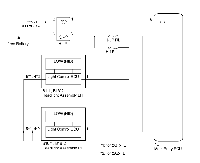
The main body receives the light control switch HEAD signal to control the headlight relay.
-
When the light control switch is in AUTO position, the main body ECU receives the ambient light level signal from the automatic light control sensor to control the headlight relay.
WIRING DIAGRAM
INSPECTION PROCEDURE
PROCEDURE
-
PERFORM ACTIVE TEST USING INTELLIGENT TESTER
-
Connect the intelligent tester to the DLC3.
-
Turn the engine switch on (IG).
-
Turn the intelligent tester on.
-
Enter the following menus: Body / Main Body / Active Test.
-
Check the operation.
Main Body Tester Display Test Part Control Range Diagnostic Note Headlight Relay Headlight Relay ON/OFF - OK Headlight relay operates. (Low beam headlights illuminate.)
NG 
INSPECT HEADLIGHT RELAY (H-LP) Click here
OK 
PROCEED TO NEXT SUSPECTED AREA SHOWN IN PROBLEM SYMPTOMS TABLE Click here
-
-
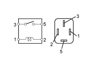
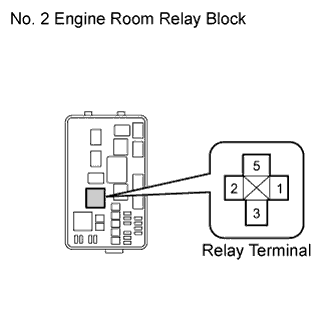
INSPECT HEADLIGHT RELAY (H-LP)
-
Remove the headlight relay from the engine room relay block.
-
Measure the resistance according to the value(s) in the table below.
Standard Resistance Tester Connection Condition Specified Condition 3 - 5 Voltage is not applied between terminals 1 and 2 10 kΩ or higher 3 - 5 Voltage is applied between terminals 1 and 2 Below 1 Ω
NG 
REPLACE HEADLIGHT RELAY
OK 
-
-
CHECK HARNESS AND CONNECTOR (BATTERY - HEADLIGHT RELAY)
-
Measure the voltage according to the value(s) in the table below.
Standard Voltage Tester Connection Condition Specified Condition Headlight relay terminal 5 - Body ground Always 11 to 14 V Headlight relay terminal 2 - Body ground Always 11 to 14 V
NG
REPAIR OR REPLACE HARNESS OR CONNECTOR
OK
-
-
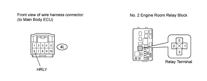
CHECK HARNESS AND CONNECTOR (HEADLIGHT RELAY - MAIN BODY ECU)
-
Disconnect the 4L main body ECU connector.
-
Measure the resistance according to the value(s) in the table below.
Standard Resistance Tester Connection Condition Specified Condition Headlight relay terminal 1 - 4L-6 (HRLY) Always Below 1 Ω 4L-6 (HRLY) - Body ground Always 10 kΩ or higher
NG
REPAIR OR REPLACE HARNESS OR CONNECTOR
OK
-
-
CHECK HARNESS AND CONNECTOR (HEADLIGHT RELAY - HEADLIGHT ASSEMBLY)
-
for 2GR-FE
-
Disconnect the B1 and B10 headlight assembly connectors.
-
Measure the resistance according to the value(s) in the table below.
Standard Resistance Tester Connection Condition Specified Condition Headlight relay terminal 3 - B1-1 Always Below 1 Ω Headlight relay terminal 3 - B10-1 Always Below 1 Ω B1-1 - Body ground Always 10 kΩ or higher B10-1 - Body ground Always 10 kΩ or higher
-
-
for 2AZ-FE
-
Disconnect the B13 and B18 headlight assembly connectors.
-
Measure the resistance according to the value(s) in the table below.
Standard Resistance Tester Connection Condition Specified Condition Headlight relay terminal 3 - B13-1 Always Below 1 Ω Headlight relay terminal 3 - B18-1 Always Below 1 Ω B13-1 - Body ground Always 10 kΩ or higher B18-1 - Body ground Always 10 kΩ or higher
-
NG
REPAIR OR REPLACE HARNESS OR CONNECTOR
OK
REPLACE MAIN BODY ECU Click here
-